APPLICATION NOTE
RCD impedance uplift elimination.
Megger Ltd, Dover, United Kingdom
www.megger.com
Sales office: 01304 502 101,
RCD impedance uplift elimination
Technical support: 01304 502 120,
P3
Higher currents reduce coil impedance but will cause the RCD to trip, preventing the test from completing.
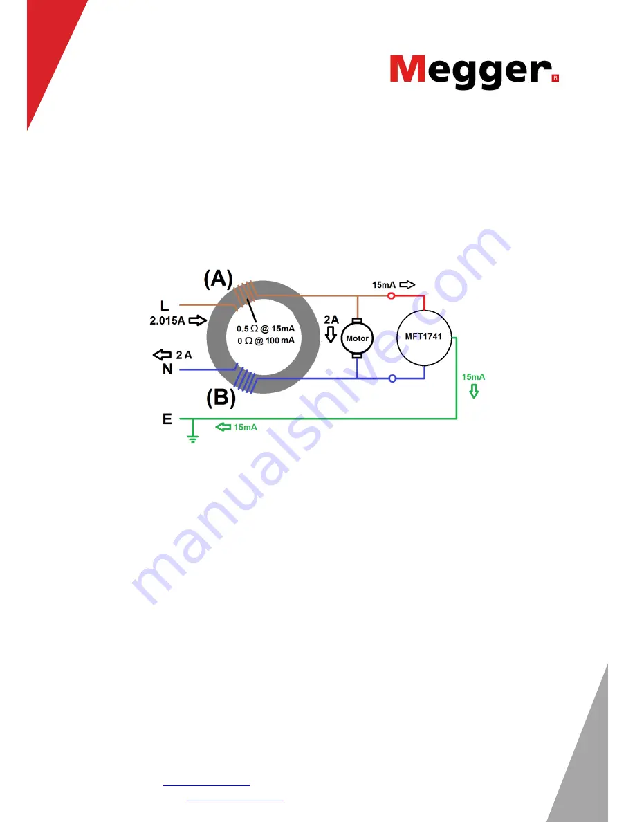
The impedance of the coil (A) at 15
mA is 0.5 Ω. This value is added to the basic circuit impedance and
the total is displayed on the MFT. The MFT cannot distinguish between the impedance of the circuit and
that of the coil.
It is irrelevant how much current is flowing in the L-N circuit. The example in Figure 3 shows the test
process in a more realistic circuit, with a motor load and a loop impedance test.
Figure 3. Test process with motor load and loop impedance test.
Still, only the difference of 15 mA is generated, the majority returning down the neutral conductor.
However this 15 mA difference is the cause of the additional impedance.
Not all RCDs or RCBOs affect the loop impedance value. However as it is not possible to distinguish
which of those devices are suspect the problem can be very confusing, annoying and time consuming.
The solution:
The new MFT1845 3-wire loop impedance test uses a combination of test currents and measurement
methods to ensure the impedance of coil (A) is not added to the circuit impedance.
By developing a range of tests within the 3-wire loop test, not only is the method immune to 30 mA RCDs
and RCBOs, the method will also work for 10 mA devices.
The new MFT can be identified by the number MFT1845 for European applications.


