DET2/3
25
Test methods and set-up
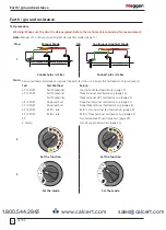
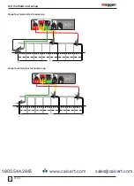
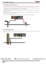
Three terminal ART test lead set-up
P1 (ES)
C2 (H)
P2 (S)
C1
CA
T IV 300V
P1
P2
C2
E
ES
S
H
I
V
E
X
Y
V
MVC1010
MVC1010
MCC1010
I
100%
62%
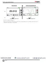
Slope method (FoP)
Description
Extract from the technical guide
Getting Down to Earth
:
It has been shown that the true earth resistance of an electrode system is obtained when the temporary potential
P is positioned at a distance from the electrical centre of the system equal to 61.8% of the distance from the
electrical centre to the temporary current probe. This principle is used in the technique called 'Intersecting Curves'
explained in
Getting Down to Earth
. It becomes apparent that the method is complex in nature and requires
some trial and error calculations.
A further technique was evolved and is described below. It is easier to use and has been shown to give
satisfactory results, both in theoretical and practical cases and when the soil is nonhomogenous. It is called the
Slope Method.
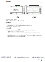
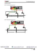
To apply the Slope Method:
1. Choose a convenient rod E to which the Earth Tester can be connected. E is one of many parallel rods
forming the complex earth system.
2. Insert the current probe at a distance (D
C
) from E (D
C
is normally two to three times the maximum dimension
of the system).
3. Insert potential probes at distances equal to 20% of D
C
, 40% of D
C
and 60% D
C
.
See examples in step 4.
4. Measure the earth resistance using each potential probe in turn. Let these resistance values be R
1
, R
2
and R
3
respectively.
Examples:
R
1
= 0.2 x D
C
R
2
= 0.4 x D
C
R
3
= 0.6 x D
C
5. Calculate the value of:
µ =
R
3
- R
2
R
2
- R
1
The resultant is called μ and represents the change of slope of the resistance / distance curve.
6. Refer to Table 1: Values of D
P
/ D
C
for various values of µ (page 27) to find the corresponding value of
D
P
/D
C
for μ.
www.calcert.com
1.800.544.2843
0
5
10
15
20
25
30


