DET2/3
7
Overview
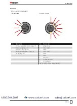
Controls
Refer to user interface (page 5).
Mode switch
Function switch
MAN
OFF
1
2
4
5
3
1
2
3
4
5
6
7
8
9
4P
4P
3P
3P
2P
A
Ω
Ω
No.
Description
No.
Description
1
Continuous graphical mode (page 11)
1
ρ
(Resistivity)
2
Manual mode (page 11)
2
4 Pole (ART)
3
Power on / off (page 10)
3
4 Pole
4
Test result management (page 33)
4
3 Pole (ART)
5
Set-up (page 12)
5
3 Pole
6
2 Pole
7
Dual clamp
8
A (leakage current)
9
Ω (continuity)
See Test methods and set-up (page 23).
www.calcert.com
1.800.544.2843
0
5
10
15
20
25
30


