


ENGLISH
ENGLISH
14
15
Installation
Installation
• If you have more than one pair of WHDI DEVICE, each transmitter and receiver should
be at least 6.5 feet away from one another. If both the transmitter and the receiver exist
in the same room, the suggested the distance between the two is 6.5 feet minimum.
• On Active mode, Press the POWER button on the top of Receiver or press RCU Power
button point to receiver, receiver enter Standby mode and transmitter’s HDMI out is
on. OSD displayed (3 sec. and then enter Standby mode).
• On Active mode, Press the POWER button on the top of Transmitter or press RCU
Power button point to transmitter, both transmitter and receiver will enter Standby
mode. OSD displayed (3 sec. and then enter Standby mode).
• Press the INFO button on the RCU, and Signal Quality, Source, Channel and resolution
will be displayed for user reference. OSD displayed (Press again for exit.)
• Press the SOURCE button on the RCU or on the top of transmitter (or receiver) for
audio/video source input selection. OSD displayed
• Press the IR button of RCU for change IR Blaster frequency, enable to switch IR Blaster
frequency 47K to 56K to 36K recurring. (Note : IR blaster frequency default setting is
47KHz). Press once for current IR frequency status display. The OSD shows:
Press IR key again to switch IR blaster frequency. The OSD shows
HDMI1 CH10 1280x1024
HDMI1 CH10 1280x1024
= OFF
1. On Screen Display (OSD) vs. RCU Instruction
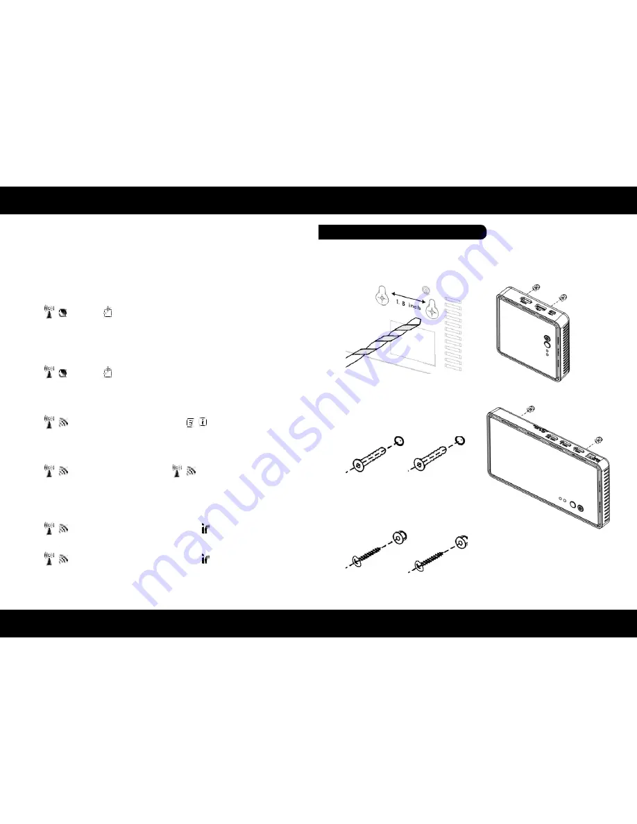
1. Refer the drawing of the bottom page
that have relative position of the main
holes and attach this paper on wall.
ON
OFF
HDMI2 CH10 1280x1024
HDMI1 CH10 1280x1024
HDMI1 CH10 1280x1024
= 47KHz
= 56KHz
NOTE:
Only the status of the RECEIVER (receiver) connected to the HDTV can be displayed on
the OSD. The status of the TRANSMITTER (transmitter) HDMI out cannot be displayed.
Step 5: Mounting the devices to the wall
2. Drill pilot holes.
3. Insert the supplied two Anchors into
the wall.
4. Insert two screws into the anchors.
Leave 1/8” length for mounting the
Transmitter or receiver.
5. Place WHDI DEVICE main holes over
the protruding screws and slide down
into position.


