21
Assembly Instructions
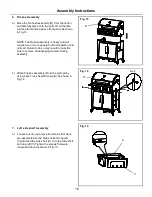
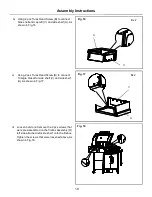
Fig. 22
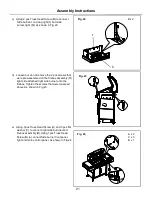
Fig. 23
c) Using 2 pcs Truss Head Screw (B) to connect
Side burnder end cap,right(T) and side
burner,right (S)).As shown in Fig.22.
d) Loosen but do not remove the 2 pcs screws that
were pre-assembled on the firebox assembly (R)
right side,attached right side burner onto the
firebox, Tighten the screws that were loosened
above,As shown in Fig.23.
e) Using 3pcs Truss Head Screw (A) and 3 pcs flat
washer (C) to connect right side burnder and
firebox assembly (R),Using 1pcs Truss Head
Screw (B) to connect Side burner front panel,
right and main control panel. As shown in Fig.24.
Fig. 24
Bx 2
A x 3
C x 3
B x 1
T
S


