


1.
2.
3.
4.
5.
1.
2.
3.
4.
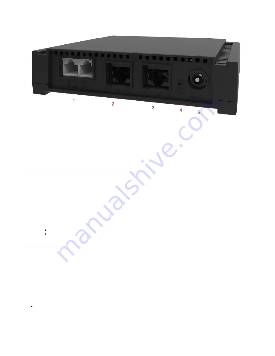
# Switch
Description
4 Reset/Default Allows setting the unit to default (known) values. Refer to
Connectors and cards
# Connectors/cards
Description
1
FXS card with 2 FXS
ports
2 x RJ-11 connectors to attach a conventional telephone or G3 fax machine.
2 LAN
10/100 BaseT Ethernet RJ-45 connector for access to a LAN, WAN or computer. This ports is used by default for LAN
connections.
3 WAN
A 10/100 BaseT Ethernet RJ-45 connector for access to a LAN, WAN or computer. This port is by default used for uplink / WAN
connection.
5 Power
External 12 Vdc 1.5 A power supply.
Top
Installing the Mediatrix Unit
Before you begin
Warning: Before performing this procedure, you must first read and understand the Safety Recommendations listed in this document.
Note: Note or take a picture of your unit's serial number before starting the installation, and place the card stickers of the cards not factory installed. Refer
to
Locating the Product Serial Number
Steps
Install the unit on a flat surface, in an equipment rack or on the wall. Refer to
Installing the Unit on a Flat Surface
Installing the Unit on the Wall
Connect the unit power cord in an appropriate AC electrical outlet.
Connect the Telephony Interface Cables. Refer to
.
Connecting the Telephony Cables
Caution: To prevent damage to the Mediatrix unit, make sure to connect the cables to their proper location on the Mediatrix unit.
Connect the Ethernet Cables. Refer to:
Verify the installation. Refer to
Top
Installing the Unit on a Flat Surface
Before you begin
Warning: Before performing this procedure, you must first read and understand the Safety Recommendations listed in this document.
Steps
Unpack the unit and go through the
Apply the Bumpon ™ autoadhesive protective products to the bottom of the unit.
Note: This will improve the airflow under the unit.
Install the unit on a flat surface.
Make sure the unit is at 20 cm (8 in.) from your monitor, computer casing, or other peripheral, including speakers.
Next Step
Connecting the Telephony Cables
Top
Installing the Unit on the Wall
Before you begin
IMPORTANT: Before performing this procedure, you must first read and understand the Safety Recommendations listed in this document.