4
PMG3 instruction manual - July 2011 rev. 01
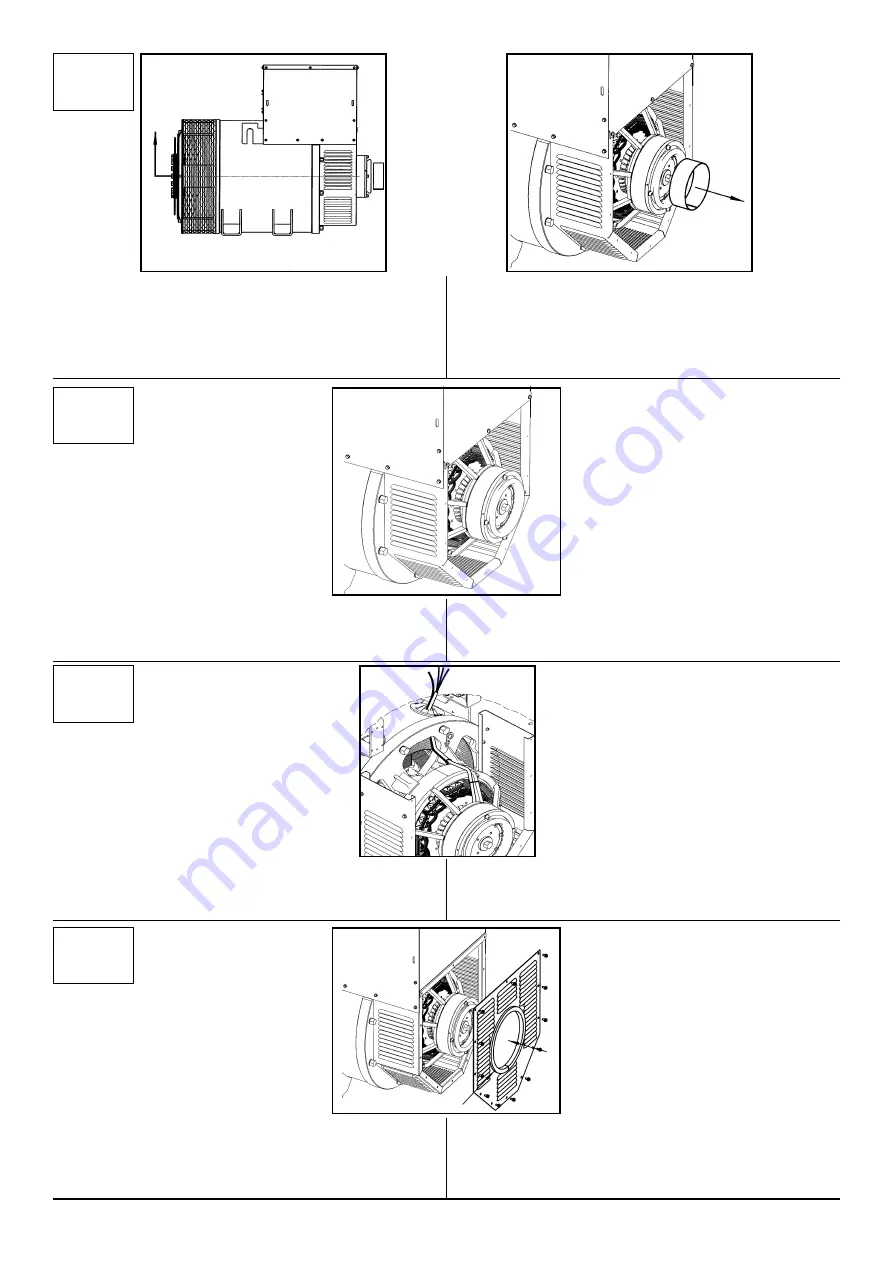
8) Verify that the "PMG ma" is perfectly located,
checking that the rotor part turns freely without any
interference.
7
7) Remove the separator suitably interposed
between the stator and rotor of the "PMG ma”.
If the generator is not coupled, slightly lift the shaft
end to facilitate the extraction of the separator.
10
10) Inserire la griglia IP23 posteriore e avvitare le 12
viti con una coppia di 9 Nm, prestando attenzione
alla guarnizione che deve rimanere bene in sede ed
interposta tra la griglia e il “PMG ma”.
10) Place the rear grid IP23 and tighten the 12
screws with a torque of 9 Nm, paying attention to the
gasket which shall remain in place and well interpo-
sed between the grid and the "PMG ma".
8
8) Verificare che il “PMG ma” sia perfettamente in
sede controllando che la parte rotante giri libera-
mente senza alcuna interferenza.
9
9) Passare i fili del “PMG-ma” come illustrato in
figura e collegarli al regolatore come indicato nello
schema a seguito
9) Pass the wires of the “PMG ma” as indicated in
the illustration, connect them to the regolator fol-
lowing the electrical scheme
7) Rimuovere il separatore opportunamente interpo-
sto tra statore e rotore del “PMG ma”; se il genera-
tore non è accoppiato, sollevare leggermente l’estre-
mità albero per facilitare l’estrazione del separatore
del “PMG ma”.


