


“SE
Series
” Service and Parts Manual
March
201
7
Page 1-11
F
R E Q U E N T
I
N S P E C T I O N
C
H E C K L I S T
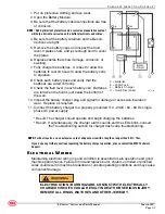
9. Turn the key switch to platform control.
10. Raise the platform and return the Maintenance Locks to the stowed position.
11. Working at the platform controls, press the lift function select button. Lower the plat-
form to the stowed position.
• Result: The diagnostic display will show code 18, an alarm sounds and the lift function should
not operate. The machine is functioning properly.
• Result: The diagnostic display does not show code 18, the alarm does not sound and the lift
function operates. Replace the Down Limit Switch.
12. Press the drive function select button. Attempt to drive the machine.
• Result: The diagnostic display will show code 18, an alarm sounds, and the steer and drive
functions should not operate. The machine is functioning properly.
• Result: The diagnostic display does not show code 18, the alarm does not sound, and the
steer and drive functions operate. Replace the Down Limit Switch.
13. Press the lift function select button. Raise the platform approximately 12 in / 0.3 m.
• Result: The diagnostic display will show code 18 and an alarm sounds. The machine is func-
tioning properly.
• Result: The diagnostic display does not show code 18 and the alarm does not sound. Replace
the Down Limit Switch.
14. Raise the platform until the pothole guards are deployed.
• Result: The diagnostic display does not show code 18 and the alarm does not sound. The
machine is functioning properly.
• Result: The diagnostic display shows code 18 and an alarm sounds. Replace the Down Limit
Switch.
15. Set the Maintenance Locks (see the Introduction portion of this manual).
DEATH OR SERIOUS INJURY HAZARD! NEVER PERFORM WORK OR
INSPECTION ON THE MACHINE WITH THE PLATFORM ELEVATED
WITHOUT FIRST BLOCKING THE SCISSOR ASSEMBLY WITH THE
MAINTENANCE LOCK.
16. Turn the key switch to the off position.
17. Disconnect the platform controls from the ECU cable.
18. Securely install the connector of the ECU cable into the platform control cable.
19. Working at the platform, securely install the connector of the platform controls into the
platform control cable.
20. Securely connect the two wires of the down limit switch to wire harness.
21. Close and install the switch cover.
22. Turn the key switch to platform control.
23. Raise the platform and return the Maintenance Locks to the stowed position.
24. Lower the platform to the stowed position.
Summary of Contents for 1930SE
Page 23: ... SE Series Service and Parts Manual March 2017 NOTES ...
Page 39: ...March 2017 Page 1 16 SE Series Parts Section NOTES ...
Page 55: ... SE Series Service and Parts Manual March 2017 Page 2 16 NOTES ...
Page 102: ...March 2017 Page A 34 SE Series Parts Section Motor Controller 1930SE SE Series ART_5197 ...
Page 114: ...March 2017 Page A 46 SE Series Parts Section NOTES ...
Page 118: ...March 2017 Page B 4 SE Series Parts Section Scissor Assembly 1930SE SE Series ART_5258 ...
Page 128: ...March 2017 Page B 14 SE Series Parts Section NOTES ...
Page 154: ...March 2017 Page C 26 SE Series Parts Section NOTES ...
Page 156: ...March 2017 Page D 2 SE Series Parts Section Lower Lift Cylinder Assembly SE Series ART_5285 ...
Page 170: ...March 2017 Page D 16 SE Series Parts Section NOTES ...
Page 178: ...March 2017 Page E 7 SE Series Parts Section NOTES ...
Page 188: ...March 2017 Page F 10 SE Series Parts Section NOTES ...
Page 193: ...NOTES ...


