background image

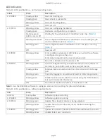
LED status indicators

The WebDAQ has four LEDs on the rear panel that indicate the status of power and host communica ons. The

following table defines the LED states during normal opera on.

LED states – normal opera ng mode

Label

State

Descrip on

1: POWER

Steady yellow

Device is boo ng up

Steady green

Device boot is successful.

Blinking yellow

Device is shu ng down.

Off

Device is off.

2: STATUS

Blinking yellow

Device is configuring hardware.

Steady green

Hardware configura on is complete.

Flashing green

100 ms on/2s off)

Wai ng for a scheduled start condi on to be met.

Blinking heartbeat

Scheduled start condi on is met; wai ng for job start

condi on to be met.

Blinking green

Data is being acquired (job start condi on is met).

Off

No error detected.

3: ERROR

Blinking yellow

Error condi on is detected. This LED blinks even when the

so ware is configured to ignore the error.

Error state is cleared when the next schedule starts.

Off

No error detected.

4: MEDIA

Blinking yellow

A job is configured to log to external media, but the job

hasn't started yet; pushbu on will not let you eject media.

Steady yellow

External media is inserted into the SD card slot or USB

storage port.

Blinking green

Currently logging to an external SD card or USB storage

device.

Steady green

Media has been made safe for removal using the func on

bu on, but has not been removed.

WebDAQ 316 User's Guide

page 14

Summary of Contents for WebDAQ 316

Page 1: ...this publica on may be reproduced stored in a retrieval system or transmi ed in any form by any means electronic mechanical by photocopying recording or otherwise without the prior wri en permission...

Page 2: ...distributor Refer to the Interna onal Distributors sec on on our website at www mccdaq com Interna onal Hazardous voltages Take the following precau ons if you connect hazardous voltages to the WebDA...

Page 3: ...such as a phone or tablet Remote monitoring and control Run simple to complex logging opera ons Flexible task scheduling Powered by Raspberry Pi The WebDAQ is designed with the Raspberry Pi Compute M...

Page 4: ...request from info mccdaq com Unpacking As with any electronic device you should take care while handling to avoid damage from sta c electricity Before removing the board from its packaging ground your...

Page 5: ...use the web interface to con gure the WebDAQ for wireless communica on Refer to the Con guring the WebDAQ for wireless communica on sec on for more informa on Connec ng directly to a PC Connect one en...

Page 6: ...browser window and enter h p webdaq xxxxxx local where xxxxxx is the last 6 digits of the MAC address The MAC address is on a label at the bo om of the WebDAQ enclosure If your network is con gured fo...

Page 7: ...y need to reboot the opera ng system and restart the WebDAQ using the Power bu on Con guring the network router for communica on across networks To communicate with the WebDAQ over the internet from a...

Page 8: ...ngs To restore network con gura on and security se ngs to the factory default values use a paper clip to press the CONFIG RESET bu on When pressed the default network and security se ngs are wri en t...

Page 9: ...nal block diagram Device func ons are illustrated in the block diagram shown here Figure 2 Func onal block diagram Front panel components Figure 3 Front panel 1 Screw terminal 2 Spring terminal WebDAQ...

Page 10: ...channels are pulled high to 5 V Any digital bit can be con gured with the web interface as a trigger to start or stop an acquisi on to trigger an alarm and be driven high or low when an alarm or occu...

Page 11: ...ents Observe the following guidelines to minimize thermal gradients and improve system accuracy Use small gauge thermocouple wire Smaller wire transfers less heat to or from the terminal junc on Run t...

Page 12: ...te for o set errors Cold junc on accuracy Heat dissipated by nearby heat sources can cause errors in thermocouple measurements by hea ng the WebDAQ 316 terminals to a di erent temperature than the col...

Page 13: ...be lost when powering down using this method Press for approximately 1 second to reboot the device release the bu on when the POWER LED blinks yellow Refer to Power On Mode for the procedure to remov...

Page 14: ...duled start condi on is met wai ng for job start condi on to be met Blinking green Data is being acquired job start condi on is met O No error detected 3 ERROR Blinking yellow Error condi on is detect...

Page 15: ...media is plugged into the WebDAQ the opera ng system opens it for wri ng Use the FUNC bu on or web interface to unmount the SD card before removing Factory reset bu on The recessed bu on labeled CONF...

Page 16: ...of the selected storage loca on a File too large error is returned and the acquisi on stops To avoid interrup ons select a storage loca on with a large capacity Logging data to external media Acquiri...

Page 17: ...ging op on for each job to Append Date Time to File Name so that each run a er power loss creates a new data le rather than overwri ng the original le Refer to the WebDAQ help for details about how to...

Page 18: ...from the Device window Device Info tab on the web interface Upda ng WebDAQ rmware Device rmware is bundled with the opera ng system web server and documenta on in a so ware update swu le Firmware upda...

Page 19: ...speed mode based on the requested scan rate regardless of the number of channels High resolu on requested scan rate is 1 Hz High speed requested scan rate is 1 Hz Timing mode High resolu on Conversio...

Page 20: ...nge in temperature that a sensor can detect It is a func on of noise The values assume the full measurement range of the standard thermocouple sensor per ASTM E230 87 Table 2 Temperature accuracy spec...

Page 21: ...Thermocouple Types J and N Errors Thermocouple Type K Errors WebDAQ 316 User s Guide page 21...

Page 22: ...Thermocouple Type T and E Errors Thermocouple Type B Errors Thermocouple Type R and S Errors WebDAQ 316 User s Guide page 22...

Page 23: ...ded min Output voltage range 0 V to 5 V no external pull up resistor 0 V to 15 V max Note 2 Output o state leakage current 10 A max Output sink current capability 100 mA max con nuous per output pin O...

Page 24: ...on Network IP con gura on DHCP link local sta c DHCP may be disabled by the user and a sta c IP address assigned If DHCP is enabled but is unsuccessful at obtaining an IP address the device will fall...

Page 25: ...label on the underside of the device Note 3 Shared folders and mapped drives are reset when factory defaults are restored Processor Memory Table 7 Processor memory speci ca ons Parameter Speci ca on M...

Page 26: ...MEDIA Blinking yellow A job is con gured to log to external media but the job hasn t started yet push bu on will not let you eject media Steady yellow External media is inserted into the SD card slot...

Page 27: ...FUNC Dual func on Ejects or safely unmounts all removable media for safe removal from the device default This func on is disabled when a job that uses external media is running The MEDIA LED is stead...

Page 28: ...to maintain me of day clock when device is powered o Note 7 If using a di erent supply ensure that it has a posi ve center pin Mechanical Table 15 Mechanical speci ca ons Parameter Speci ca on Dimens...

Page 29: ...e 115 V for US or 230 V for Europe Cau on Do not connect the device to signals or use for measurements within Measurement Categories III or IV Signal connectors Table 18 Screw terminal speci ca ons Pa...

Page 30: ...Channel 5 HI 35 TC5 Channel 5 LO 8 TC6 Channel 6 HI 36 TC6 Channel 6 LO 9 TC7 Channel 7 HI 37 TC7 Channel 7 LO 10 TC8 Channel 8 HI 38 TC8 Channel 8 LO 11 TC9 Channel 9 HI 39 TC9 Channel 9 LO 12 TC10 C...

Page 31: ...w Voltage Direc ve 2014 35 EU RoHS Direc ve 2011 65 EU Conformity is assessed in accordance to the following standards EMC Emissions EN 61326 1 2013 IEC 61326 1 2012 Class A EN 55011 2009 A1 2010 IEC...

Page 32: ...Measurement Compu ng Corpora on 10 Commerce Way Norton MA 02766 Phone 508 946 5100 mccdaq com support WebDAQ 316 User s Guide page 32...

Reviews: