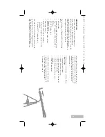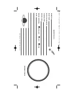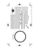
FIGURE 1
Figur
e 1
:
T
el
es
tar 60AZ-A2 Alt
azimuth Refr
acting T
e
lesc
ope
Inset A
:
A
c
c
e
s
sory T
ray Mounting Bolt Hol
e
Inset B
:
T
ripod Leg
Inset C
:
Viewfinder As
sembl
y
1.
Ey
epiec
e
2.
Viewfinder (see Inset C)
3.
Viewfinder alignment scr
e
ws (see Inset C)
4.
Optic
al tube as
sembl
y
5.
V
ertic
al l
ock knobs
6.
Horizont
al l
ock knob
7.
T
ripod l
egs
8.
Leg br
ac
e supports
9.
Leg br
ac
e
10.
Mount base att
achment
11.
T
ripod att
achment bolts and wing nuts
12.
Ac
c
e
s
sory tr
ay mounting bolt hol
e (see Inset A)
13.
Diagonal mirr
or
14.
Objectiv
e
l
ens c
ell
15.
F
ocuser dr
awtube and thumbscr
e
w
s
16.
Altitude r
od sl
o
w
motion fine adjus
tment c
o
ntr
ol
17.
Altitude r
od
18.
Alt
azimuth mount
19.
Adjus
tabl
e sliding c
ent
er l
eg e
x
tension
(see Inset B)
20.
T
ripod l
eg l
ock thumbscr
e
w
(see Inset B)
21.
Dew shield/l
ens shade
22.
F
ront l
ens c
a
p
23.
F
ocusing knob
24.
Viewfinder br
ack
et (see Inset C)
25.
Viewfinder br
ack
et mounting thumbscr
e
w
s
(see Inset C)
26.
Ac
c
e
s
sory tr
ay
2
Inset A
Inset B
Inset C
b
c
d
e
f
g
h
i
i
j
1)
1*
1!
1@
1#
1$
2!
2)
1(
c
d
2%
2$
2@
2^
1%
2#
1^
1&
40-04135 8 Page Manual Template 6/29/05 10:54 AM Page 4


