
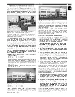
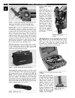


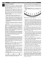


4. Each table tripod is equipped with two
adjustable tripod legs: The standard tripod
leg is used at observing latitudes as shown in
the box in step 5 and has a dual latitude label
attached (Fig. 15). The high-latitude tripod
leg is shorter and is used at higher observing
latitudes. Based on the observing latitude
determined in step 3, set aside the tripod leg
that is not to be used.
5. Locate the two mounting holes on the bottom
of the telescope drive base. Mount the
appropriate adjustable tripod
leg (as
determined in step 4) to the drive base using
the following latitudes:
Standard Tripod Leg (ETX-90EC)
32.5° to 48.5° uses high-latitude hole
(2, Fig. 16).
22° to 35.5° uses alternate hole
(3, Fig. 16).
High-Latitude Tripod Leg (ETX-90EC)
56° to 66° uses high-latitude hole.
44° to 55° uses alternate hole.
Standard Tripod Leg (ETX-125EC)
33.5° to 49.5° uses high-latitude hole.
23.25° to 36.5° uses alternate hole.
High-Latitude Tripod Leg (ETX-125EC)
56.6° to 67° uses high-latitude hole.
44.5° to 56.5° uses alternate hole.
Thread the appropriate leg into the required
hole to a firm feel only.
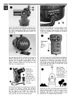
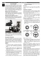
6. A small thumbscrew (6, Fig. 16) is attached to
both the standard and high-latitude tripod
legs. Loosening the thumbscrew allows the
outer section of the leg to slide over the inner
section, so that the leg can be extended. If
using the standard tripod leg, extend the leg
so that the center of the thumbscrew head
aligns with the latitude of the observing
location on the scale. Retighten the
thumbscrew to a firm feel. (If using the high-
latitude tripod leg, complete the adjustment of
the leg extension in step 9.)
Example: The latitude of New York City is 41°.
The tripod leg should be extended so that the
center of the thumbscrew is set next to the 41°
reading on the scale.
CAUTION:When using the #880 Table Tripod
with the ETX-90EC, the optional #1422 Low-
Latitude Balance Weight is recommended if
the telescope is to be polar aligned below 30°, or if heavy
accessories are attached to the eyepiece-end of the
telescope. The low-latitude balance weight is recommended
for the ETX-125EC at all observing latitudes and is included
as standard equipment with the #881 Table Tripod.
NOTE:With the standard tripod leg threaded into the appropriate
hole in the dri ve base, the latitude scale may be at an
inconvenient position for reading (e.g., the scale faces the drive
base). This situation can be remedied by unthreading the leg,
removing the thumbscrew, rotating the inner leg 180°, then
reinserting the thumbscrew. The scale should now be readable
when threaded back into the telescope base.
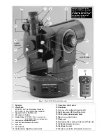
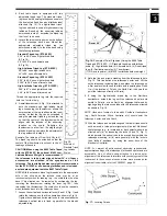
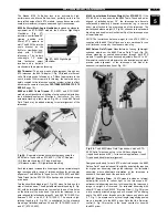
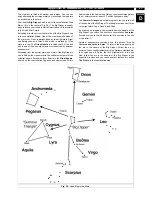
7. Loosen the vertical and horizontal locks (6 and 10, Fig. 1) and
rotate the telescope so that it is oriented as shown in Fig. 16.
Tighten the vertical and horizontal locks. In this orientation the
telescope’s optical tube is lined up parallel to the tripod’s
adjustable leg.
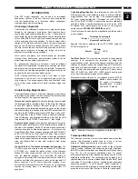
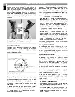
8. Note the line and arrow extending from the telescope tube in
Fig. 16. This line defines the telescope’s polar axis. Lift the
entire telescope, including tripod, and place the telescope on
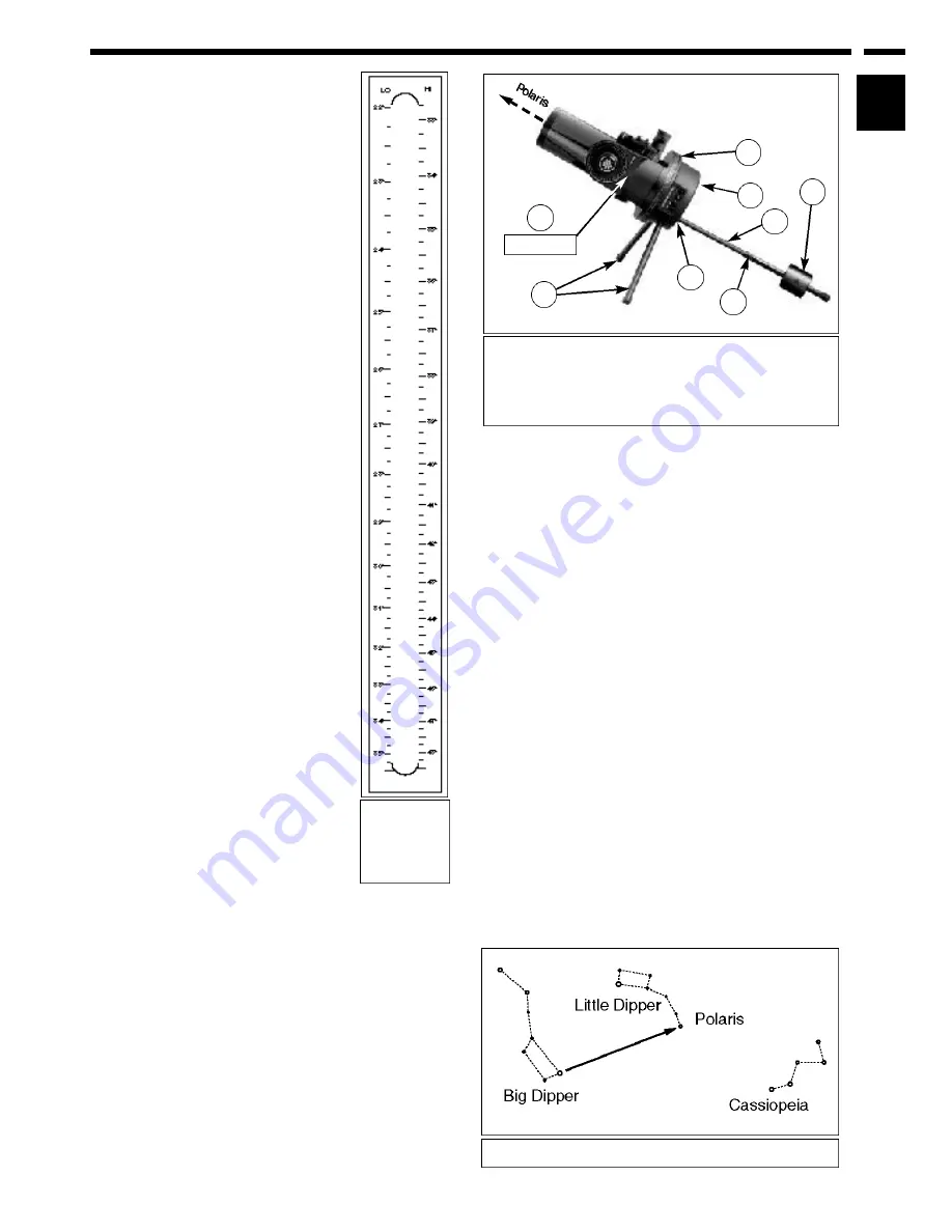
a firm and level surface so that this axis is pointing due North
(i.e., if the location of Polaris, the North Star, is known then
point the telescope directly at Polaris).
9. If using the high-latitude tripod leg in the Northern
hemisphere, extend the leg until the telescope’s polar axis
points to Polaris, or due North, an alignment obtained by
sighting along the telescope tube with the telescope oriented
as shown in Fig. 16.
NOTE: Observer’s located in the earth’s Southern Hemisphere
(e.g., South America, Africa, Australia, etc.) should point the
telescope’s polar axis due South.
10.With the telescope now polar-aligned the table tripod should
not be moved, or else polar alignment will be lost. Motions of
the telescope (e.g., to locate and/or track objects) should be
effected only (a) by loosening the locks (6 and 10, Fig. 1),
which permits the optical tube to be moved freely within the
telescope mounting, or (b) more generally, with the locks in
their “locked” positions, by using the arrow keys of the
Electronic Controller.
NOTE: For almost all astronomical observing requirements,
approximate settings of the telescope’s latitude and polar axis are
a c c e p t a bl e. Do not allow undue attention to precise polar
alignment of the telescope to interfere with your enjoyment of the
instrument. In those unusual cases where more precise polar
alignment is desirable, refer to APPENDIX C, page 24.
13
POLAR ALIGNMENT
CHAPTER
3
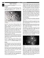
Fig. 17: Locating Polaris.
Fig.15:
Example of
Standard Tripod
Leg Latitude
Scales.
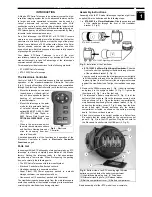
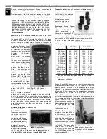
Fig.16: Example of Polar Alignment Using the #880 Table
Tripod and ETX-90EC. (1) Standard tripod leg with latitude
scale; (2) High-latitude hole; (3) Alternate hole; (4) Fixed tripod
legs; (5) Declination pointer; (6) Thumbscrew;
(7) R.A. scale pointer; (8) #1422 low-latitude balance weight.
6
2
Dec.at 90°
1
5
4
7
3
8


