Document No 7202-D0001-12
15
INSTALLATION - continued
9.
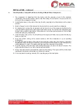
Check Operation
– Setup & Performance Testing of Diesel Driven Compressor.
1
The compressor is dispatched from the factory with the pressure pre-set to the customer
specification. Should the customer want to alter this setting, the instruction on how to do this can
be found in the compressor manual.
2
Install the ball valve on the outlet of the hose from the compressor. Set the ball valve to the closed
position.
3
Refer to Pages 7 and 8 of this manuals for the method to be used to start the compressor.
4
On starting and running, the air pressure will be found to be at the pressure specified by the
customer and the engine will be at the lower speed (idle speed). The Unit has been adjusted by the
factory to the customer specification. If the pressure is not at the specified pressure, refer to MEA
before attempting any adjustments.
5
Listen for leaks in the air line. You should hear a hissing sound if there are any leaks. Rectify any
leaks you may find.
6
Keep the system running at the pre-set pressure until the compressor is up to operating
temperature.
7
Using the ball valve located on the outlet of the compressor, slowly open the ball valve, and watch
the pressure drop. The pressure will drop up to the point that the pressure is 20 PSI below the
setting detailed in 1 above. The engine will speed up to the maximum pre-set RPM.
8
Keep the opening of the ball valve at the setting described in (7) above for about 5 minutes. The
engine should continue to run at the maximum pre-set RPM.
9
Slowly close the ball valve and watch the pressure while closing. The engine will drop to the lower
speed when the pressure described in (1) above is reached.
10 Your compressor is working correctly if it is operating as per this description
Summary of Contents for SMAC 35DG/BFM
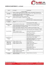
Page 2: ...Document No 7202 D0001 12 THIS PAGE IS LEFT BLANK INTENTIONALLY ...
Page 8: ...Document No 7202 D0001 12 4 INTRODUCTION continued ...
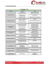
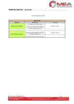
Page 23: ...Document No 7202 D0001 12 19 8 TROUBLESHOOTING ...
Page 24: ...Document No 7202 D0001 12 20 TROUBLESHOOTING continued ...
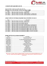
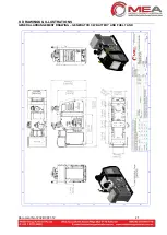
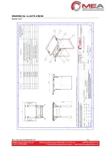
Page 26: ...Document No 7202 D0001 12 22 DRAWINGS AND ILLUSTRATIONS PARTS LIST ...
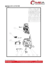
Page 27: ...Document No 7202 D0001 12 23 DRAWINGS ILLUSTRATIONS PARTS LIST ...
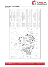
Page 28: ...Document No 7202 D0001 12 24 DRAWINGS ILLUSTRATIONS PARTS LIST ...
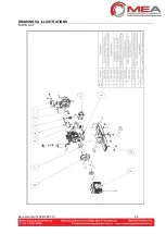
Page 29: ...Document No 7202 D0001 12 25 DRAWINGS ILLUSTRATIONS PARTS LIST ...
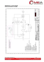
Page 30: ...Document No 7202 D0001 12 26 DRAWINGS ILLUSTRATIONS HYDRAULIC PNEUMATIC DIAGRAM ...
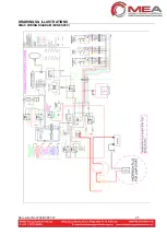
Page 31: ...Document No 7202 D0001 12 27 DRAWINGS ILLUSTRATIONS SMAC WIRING DIAGRAM MINE SPEC ...
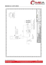
Page 32: ...Document No 7202 D0001 12 28 DRAWINGS ILLUSTRATIONS ...
Page 34: ...Document No 7202 D0001 12 30 DRAWINGS ILLUSTRATIONS ...


