background image

This product is covered by a limited warranty that is effective for 90 days from the date of purchase. If, 

during the limited warranty period, a part is found to be defective or broken, we will offer replacement parts 

at no cost to you, the customer. The only exceptions to the warranty include main frames, table tops, 

playing surfaces, batteries or tools. 

The above warranty will not apply in cases of damages due to improper usage, alteration, misuse, abuse, 

accidental damage or neglect. 

This Limited Warranty gives you specific legal rights and you may also have other rights which vary from 

one State (province) to another.

A PURCHASE RECEIPT (or other proof of purchase date) will be required before any warranty service is 

initiated. For all requests for warranty service, please feel free to contact our Consumer Service Department 

at :

Please be aware of your product’s Limited Warranty for the return/refund policy from the store, We, at Medal 

Sports, can not handle the product which is out of product’s limited warranty since we only provide available 

parts. Thank you!

PLEASE  CONTACT US BEFORE RETURNING 

THE PRODUCT TO THE STORE.

WEBSITE: www.themdsports.com

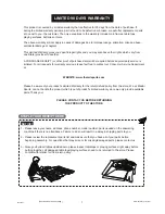
NOTICE!

STAPLE YOUR RECEIPT HERE 

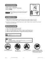
1 - Please leave your name, address, phone number, model number, parts needed on the answering

     machine if there is no attendance. Failure to do so will result in a delay in shipping parts to you.

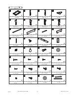
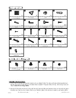
2 - Please review the replacement parts list and make sure that you have all of your parts before 

beginning assembly. For questions that may arise or for missing/damaged parts, please contact us.

3 - Since you build all tables upside down, please inspect tabletops or playing surfaces right away before 

      putting together, all damaged table tops/playing surfaces need to be returned to the store. Please 

      contact with retailer for their return policy. 

LIMITED 90 DAYS WARRANTY

www.themdsports.com

1439021

1

(Continued on the next page.)

Summary of Contents for 1439021

Page 1: ...MODEL 1439021 VM Innovations ASSEMBLY INSTRUCTIONS TM Register Now on themdsports com and Earn a One Year Warranty for Free Please contact us before returning the product to the store ...

Page 2: ...nd Receive A FREE FULL YEAR EXTENTED WARRANTY Write a review for a recently purchased item on TheMDSports com and receive an extended full year limited warranty valued at 150 00 See TheMDSports com for additional details TM ...

Page 3: ... your product s Limited Warranty for the return refund policy from the store We at Medal Sports can not handle the product which is out of product s limited warranty since we only provide available parts Thank you PLEASE CONTACT US BEFORE RETURNING THE PRODUCT TO THE STORE WEBSITE www themdsports com NOTICE STAPLE YOUR RECEIPT HERE 1 Please leave your name address phone number model number parts n...

Page 4: ...ly Required ASSEMBLY TIPS 1 Please read the instructions carefully and follow all assembly operation and safety instructions properly in order to avoid damage or injury For the assembly at least four adults are required 2 Some figures or drawings may not look exactly like your product Please read and understand the text before beginning each assembly step 1 This product is intended for INDOOR use ...

Page 5: ... Base Plastic Leg A Plastic Leg B Plastic Leg C Plastic Leg D Side Top Board Lower Side Apron End Top Board Lower End Apron Corner Brace Leg Top Panel Support Board U Plastic Bracket Steel Bracket F4 x 1 1 2 Screw P3 x 1 2 Screw T4 x 1 2 Screw T4 x 5 8 Screw F3 x 5 8 Screw 5 16 x 1 Bolt 5 16 x 1 2 Bolt 1 4 x 1 1 2 Bolt 1 4 Nut 1 4 x 1 Bolt 1 4 Washer 57 Cue Glue 5 16 x 1 1 2 Bolt 5 16 Washer www t...

Page 6: ...5 16 T Nut 1439021 PARTS LIST 1439021 PRE INSTALLED PARTS ASSEMBLY INSTRUCTIONS 1 Find a clean level place to begin the assembly of your Billiard Table The table will be assembled upside down and then turned over on its legs once the assembly completed This game table is heavy and turning it over will require at least four strong adults 2 Remove all the parts from the box and verify that you have ...

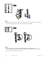
Page 7: ... FIG 1 FIG 2 5 Attach the Leg Bases 4 to the grooves using two Screws 40 per Leg Base See FIG 2 Note Do not place the wrong surface of the Leg Base 4 when you assemble the Leg Leveler 39 6 Screw the Leg Levelers 39 into the Leg Bases 4 16 26 2 3 40 FIG 2 X 4 X 8 X 4 4 39 40 X 4 X 8 X 16 X 16 X 4 2 3 16 26 40 FIG 1 39 4 40 www themdsports com 1439021 5 Continued on the next page ...

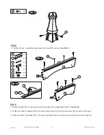
Page 8: ...ssembling the Plastic Legs Over tightening ofthe screw can cause damage to the leg FIG 4 22 7 8 and 2 3 and 5 6 and FIG 3 7 Carefully align the seams of the Plastic Legs A 5 and Plastic Legs B 6 lock them using locking pieces on the legs Note Listen to the sound of click when locking the legs together to ensure the legs are locked firmly 8 Next lock the Plastic Legs C 7 and Plastic Legs D 8 togeth...

Page 9: ...the grooves of the Side and End Top Boards 9 11 See FIG 6A 13 Attach the Side Top Boards 9 to the Lower Side Aprons 10 using four Screws 21 per Side Top Board 14 Attach the End Top Boards 11 to the Lower End Aprons 12 using three Screws 21 per End Top Board FIG 5 FIG 6 23 FIG 6A 9 18 11 21 12 11 P4 10 21 9 www themdsports com 1439021 7 Continued on the next page P4 ...

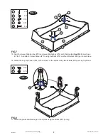
Page 10: ...12 10 11 9 27 P4 FIG 7 15 Align the Lower Side Aprons 10 and Lower EndAprons 12 with Top Boards See FIG 6 as shown in FIG 7 And attach Corner Braces 13 using fourBolts 19 and four Washers 20 per corner brace 16 Attach the Leg Top Panels 14 to the corners of the aprons using two Screws 25 per Leg Top Panel www themdsports com 1439021 8 Continued on the next page P4 ...

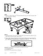
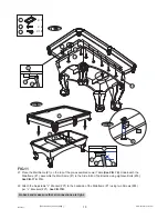
Page 11: ...ease note that L Brackets P1 Support Board 15 are parallel as shown in FIG 10A P1 28 17 31 29 15 FIG 9 FIG 10 P1 P1 24 10 17 10 15 15 15 FIG 10A FIG 9 18 Attach the U Plastic Brackets 17 to the Support Boards 15 using one Bolt 28 one Washer 31 and one Nut 29 per U Bracket DO NOT LEAN THE TABLE ON ITS LEGS HOLD TABLE HOLD TABLE DO NOT HOLD THE LEGS CAUTION Four strong adults are recommended to turn...

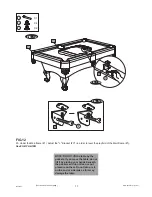
Page 12: ...ainframe 1 on the top of the pre assembled Lower Table See FIG 10 Underneath the Mainframe 1 assemble the Mainframe 1 to the Side End Top Boards using eighteen Bolts 30 See FIG 11 11A 22 Attach the Adjustable L Bracket P1 to the backside of the Mainframe 1 using two Screws 24 per L Brackets P1 See FIG 11B www themdsports com 1439021 10 Continued on the next page ...

Page 13: ... it by placing your hands beneath the pockets and do not lean or put pressure on them Do not lean or sit on the end or side rails as this may damage the table FIG 12 23 Under the Mainframe 1 adjust the L Bracket P1 in order to level the playfield of the Mainframe 1 See FIG 12A 12B www themdsports com 1439021 11 Continued on the next page ...

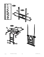
Page 14: ...4 X 5 40 23 41 X 1 42 X 1 43 X 2 44 X 1 45 X 1 46 X 2 47 X 2 48 X 1 49 FIG 13 40 40 42 43 44 FIG 13A 40 40 40 23 23 41 41 45 46 47 47 48 48 49 FIG 13B www themdsports com 1439021 12 Continued on the next page ...

Page 15: ...s 40 See FIG 13B 26 Attach the Cue Rack Hooks 47 to the Cue Rack Top Panel 45 using two Screws 23 per Hook See FIG 13B 27 Attach the Cue Holders 48 to the Cue Rack Top Panel 45 using two Screws 41 per Holder See FIG 13B 28 Attach the Triangle Holder 49 to the Cue Rack Top Panel 45 using one Screw 23 See FIG 13B 29 Attach the Cue Rack Top Panel 45 to the Cue Rack Left Side 42 and Cue Rack Right Sid...

Reviews: