background image

63

14-TROUBLESHOOTING

Technical Dept. - All rights reserved - Reproduction is prohibited

ANOMALY

POSSIBLE CAUSES

SOLUTIONS

The air fan does not switch on.

The product has not reached the 

temperature.

Wait.

The (optional) remote control does 

not work.

The remote control battery is flat.

Replace the battery.

Remote control faulty.

Replace the remote control.

The product always runs at maximum 

power when in automatic mode.

The room thermostat is in the maximum 

position.

Reset the temperature of the remote 

control.

Malfunctioning temperature probe.

Check the probe and replace it if 

necessary.

Faulty or malfunctioning control panel.

Check the panel and replace if necessary.

The product does not switch on.

No power supply.

Check that the plug is inserted and the 

main switch is in the “I” position.

Fuse tripped due to a fault.

Replace the fuse with one with same 

characteristics (5x20 mm F 3.15A).

Check the brazier.

Clean the brazier and remove any deposits 

or residues of non-burned pellets.

Check the position of the brazier.

Put the brazier back in its place.

Check that the ignition plug warms up.

Check and if necessary, replace.

Clogged smoke outlet or smoke duct.

Clean the smoke outlet and/or the smoke 

duct.

Faulty ignition plug.

Replace the ignition plug.

Summary of Contents for AMY Air

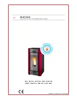
Page 1: ...INSTALLATION GUIDE EN SEALED PELLET STOVE AMY Air Instructions in English...

Page 2: ...3 DRAWINGS AND TECHNICAL FEATURES 17 4 INSTALLATION AND ASSEMBLY 19 5 CONNECTION TO ADDITIONAL DEVICES 28 6 LOADING THE PELLETS 29 7 FIRST START UP 30 8 CONTROL PANEL 31 9 OPERATION 38 10 SAFETY DEVIC...

Page 3: ...alled By system one means Stove Chimney Air inlet REVISIONSTOTHE PUBLICATION The content of this manual is strictly technical and the property of MCZ Group Spa No part of this manual may be translated...

Page 4: ...e tank The instructions provided in this manual must always be complied with to ensure the product and any electronic appliances connected to it are used correctly and accidents are prevented This app...

Page 5: ...en The doors covers on the appliance must remain closed when it is not used The product must be powered by an electrical system that is equipped with an effective earthing device Switch the product of...

Page 6: ...of the product willrestandprovidesuitableinsulationifitismadeofflammablematerial e g wood fitted carpet or plastic Live electrical parts only power the product once it has been fully assembled Disconn...

Page 7: ...hase invoice and or receipt that shows the name of the vendor and the date on which the purchase was made forwarding of the completed warranty certificate within 8 days of purchase Furthermore in orde...

Page 8: ...the annual stove maintenance performed by an authorised technician or qualified personnel will result in the loss of the warranty Also excluded from this warranty are parts subject to normal wear suc...

Page 9: ...ot be disposed of as urban waste It must be taken to a special differentiated waste collection centre set up by the local authorities or to a retailer that provides this service Separatingandrecycling...

Page 10: ...around 4 9 kW kg To ensure good combustion the pellets must be stored in a dry place and protected from dirt Pellets are usually supplied in 15 kg bags therefore storing them is very convenient Good q...

Page 11: ...he home The installation of the appliance must ensure easy access to clean the appliance itself the smoke exhaust pipes and the flue It is forbidden to install the stove in rooms with a fire hazard In...

Page 12: ...t as modern heating appliances have high efficiency with cooler flue gasses and consequently less draught it is therefore essential that the flue is built up to standard and always kept in perfect wor...

Page 13: ...reduce smokecooling Itshouldbeseparatedfromcombustibleorflammablematerialswithanairgaporinsulatingmaterials checkthedistance specified by the manufacturer of the fireplace according to EN1443 The chim...

Page 14: ...th a minimum radius of 20 mm The dimension of the cross section must be minimum 100mm The cross sections lengths of the chimneys shown in the technical data tables are indications for correct installa...

Page 15: ...qualified chimney sweep at least once a year Once the inspection maintenance has been performed request a written report that the system is safe Failure to perform cleaning jeopardises the system s sa...

Page 16: ...uldinterferewiththeproperflowofairtothestove see diagram below Theairinletmusthaveaminimumnettotalareaof80cm2 thesurfacemustbeincreasedaccordinglyifthereareotheractivegenerators for example electric f...

Page 17: ...ncemustbeviaasmokeductthatcomplieswithEN1856 2 Theconnectingsectionmust extend no more than 4 m horizontally with a minimum slope of 3 and with a maximum of 3 90 bends accessible for inspection do not...

Page 18: ...m safety distances from combustible materials The previous rules also apply for holes made in walls 2 Oldflue minimumpipe 100mmwiththeinclusionof an external access door for chimney cleaning 3 Externa...

Page 19: ...900 90 180 50 130 220 80 480 460 80 50 17 3 DRAWINGS ANDTECHNICAL FEATURES Technical Dept All rights reserved Reproduction is prohibited DRAWINGS AND CHARACTERISTICS AMY AIR STOVE DIMENSIONS...

Page 20: ...40 mm Pellet hourly consumption Min 0 6 kg h Max 1 45 kg h Autonomy At min 26 h At max 11 h Heatable volume m3 135 40 155 35 181 30 Combustion air inlet 50 mm Smoke outlet 80 mm Air inlet 80 cm2 Rate...

Page 21: ...ingle package Open the package remove the two screws v which secure the stove brackets to the pallet and then remove the bracket S from the stove foot There are four bracket two Q at the front and two...

Page 22: ...flue pipe Remove the plastic clamp securing the top to the stove s frame If the stove needs to be connected to an outlet pipe which goes through the rear wall to connect to the flue take utmost care t...

Page 23: ...DDING DISASSEMBLINGTHE BACK SIDE PANEL The stove is delivered fully assembled if you need to remove the side panels for technical service or cleaning proceed as follows raise the cover of the pellet t...

Page 24: ...r p A 22 4 INSTALLATION AND ASSEMBLY place the panel A in a safe place...

Page 25: ...All rights reserved Reproduction is prohibited REMOVINGTHETOP AND DISASSEMBLINGTHE FRONT SIDE PANEL To remove the top C just lift it off its four rubber mounts To remove the front side panel B remove...

Page 26: ...r s B 24 4 INSTALLATION AND ASSEMBLY raise the panel B so that the hole s slides off the stud r place the panel B in a safe place...

Page 27: ...nical Dept All rights reserved Reproduction is prohibited DISASSEMBLINGTHE FRONT LOWER PANEL Once you have removed the left and right side panels you can remove the lower panel D remove the two screws...

Page 28: ...ctronics board m is on the right side handle side If you need to access the board you must remove the back side panel as explained above ACCESSTOTHE GEARMOTOR To access the gearmotor you must remove t...

Page 29: ...production is prohibited OPENINGTHE DOOR OFTHE FIREBOX To open the firebox door fit the cold handle F into its hole in the handle and pull it outwards Attention Thefireboxdoormustbeclosedproperlyforth...

Page 30: ...tat s receiver U mounts onto the provided holes Once the receiver U has been secured with the provided screws break the knockout hole V and route the cables for connection to the board through it INST...

Page 31: ...stove mitten that comes with the stoveitself Whenloading donotletthepelletbagcomeintocontactwithhotsurfaces Neverremovetheprotectiongridinsidethetank No other type of fuel other than pellets is to be...

Page 32: ...Failure to clear out thebrazierpriortoresettingmayresultinfurtherfailedignitionsorincertainconditionsanexplosiveignition Itisgoodpracticetoensureeffectiveventilationintheroomduringtheinitialstart up...

Page 33: ...eofthe4keysnearthedisplay CDEF toenterthestove ssettingsscreen flameandventilationlevel settemperature automatic manual mode etc On this level the 4 keys around the display become dedicated functions...

Page 34: ...f any malfunction B Power on off key ON OFF or ESC exit the menu C Air fan speed and menu scroll D Access to main menu and submenus E MANUAL AUTOMATIC mode selection F Manual mode flame power setting...

Page 35: ...notused STOVE POWER SUPPLY After connecting the power cable to the back of the stove turn the switch at the back to position I The luminous switch button will light up The switch on the back of the st...

Page 36: ...y the text MENU The stove can be turned on and off by holding key B on the control panel down down for 2 seconds or by pressing button 3 on the remote control optional The startup phase lasts around 1...

Page 37: ...mode you can use the button at the bottom left F to adjust the 5 heat power values of the stove while with the one at the bottom right C you can set the speed of the fans AUTOMATIC mode allows you to...

Page 38: ...the room temperature setpoint PressTEMP F to raise the temperature by a step at a time up to 35 C after which it starts again from 5 C Hold downTemp F to enter the menu for setting the temperature wi...

Page 39: ...adjustable to 5 manual speeds and one automatic setting To select the speed after pressing the button on the bottom right press it to increase or decrease ventilation power The flame power also depen...

Page 40: ...t ups RPM evacuator T smoke Heat exchanger voltage auger loading Flame Setting the time and day Press the relative MENU key and SET will appear Enter SET and the programme will appear to change day ho...

Page 41: ...Temp 22 C Fa n A 21 0 C 21 04 OFF Esc 57 O k Minut i Esc 09 Ok Giorno num Es c 06 Ok Mese Esc 2010 Ok Anno E s c 2010 Ok Anno Mode AUTO Menu Temp 22 C Fan A 39 9 OPERATION Technical Dept All rights re...

Page 42: ...NO n alternate on the display n is the number of crono programs in use separated by dashes Example CRONO 1 only crono program 1 active or CRONO 1 4 crono programs 1 and 4 active or CRONO 1 2 3 4 5 6 a...

Page 43: ...the OFF button the stove goes into shut down and turns back on the next time a crono program starts When the stove is off and crono is active pressing the ON key turns on the stove the stove then sto...

Page 44: ...rm your selection press the key for OK top right otherwise ESC top left to exit without saving any settings IfyouactivatetheSLEEPfunctionwhenCRONO CHRONO isactive thefirstfunctionhasthepriority theref...

Page 45: ...raturerequirementachieved thetime ECOstopT startstocountdown default10minutes settableinsthetechnicalmenu by an authorised MCZ technician During this phase the panel continues to display ON ECO ON but...

Page 46: ...LET RECIPE menu Confirm with the button D next to the text SET Modify the value with the bottom buttons F and C which correspond to the symbols and Confirm with the button D corresponding to OK Availa...

Page 47: ...dbyaqualifiedtechnician ATTENTION Theelectricalwiresmustnotcomeintocontactwiththehotpartsofthestove The temperature of the stove can also be controlled by an external room thermostat It should be posi...

Page 48: ...t contact closed the stove modulates the flame towards maximum power Operating mode with external thermostat and Eco Stop WiththeexternalthermostatandECO STOPactivated thestovewillactuatetheconditions...

Page 49: ...Proceed as follows to activate it press any button on the control panel to enter the MENU press MENU scroll down to SETTINGS press SET scroll down toTELECOMANDO REMOTE CONTROL press SET select ON wit...

Page 50: ...opriatecontainers Iftheremotecontrolisoffbecauseithasnotbattery thestovecanbecontrolledwithitstop mountedcontrolpanel Whilereplacingthebattery observetheorientationmarkedinsidethebatterycompartment Au...

Page 51: ...located on the latter SMOKE FAN BREAKAGE If the fan stops the circuit board promptly blocks the supply of pellets and the alarm is displayed GEAR MOTOR BREAKAGE If the gear motor stops the product sw...

Page 52: ...eck that the brazier rests correctly in its seat and has no visible deposits of unburned pellets A03 The temperature of the pellet hopper exceeds the required safety threshold Wait until the end of th...

Page 53: ...t of a power failure the stove does the following Power failure of less than 10 continues the work in progress After a loss of power of more than 10 which occurred when the stove was on or during igni...

Page 54: ...hat the product is installed in compliance with standards in force Furthermore it is of the utmost importance to respect the following simple rules Every time the brazier is removed for cleaning it mu...

Page 55: ...ays clean the b brazier and remove any ash or incrustation from it that might obstruct the air flow holes paying attention to hot ash In the case of ignition failure or if fuel in the tank runs out un...

Page 56: ...rtment you must raise grille g by rotating until it rests against the hearth Clean out any residual ash before lowering the grille g The quality of the pellets used and user experience will determine...

Page 57: ...t becomes very difficult to remove it due to the humidity compacting it over time ATTENTION Itisobligatorytohaveanauthorisedandskilledtechnicianperformtheperiodicend of seasoncleaninginorderto replace...

Page 58: ...ing the cap for lower cleaning N see previous paragraph use a stiff rod or a bottle brush to scrape the firebox walls see arrow so that the ash falls into the lower compartment Then remove the upper C...

Page 59: ...hibited Use a stiff rod or a bottle brush to scrape the firebox walls see arrow at the right and left of the firebox respectively so that the ash falls into the lower compartment Use a vacuum cleaner...

Page 60: ...58 13 CLEANING Also vacuum under the top to remove any accumulated dust Then thoroughly clean the lower exchanger replace any gaskets if needed and reassemble...

Page 61: ...ATTENTION The frequency with which the smoke outlet system is cleaned depends on the use of the boiler and the type of installation We recommend relying on an authorised service centre for end of sea...

Page 62: ...n the presence of children Theservicefusemayhavetobereplacedifthecontrolpaneldisplaydoesnotswitchonwhentheproductisswitchedonagainbypressing the main switch on its side There is a fusebox on the side...

Page 63: ...e hopper with pellets The pellets are not fed See the previous anomaly The pellet temperature safety probe has been triggered Let the product cool down restore the thermostat until the lockout is off...

Page 64: ...eaning of the combustion chamber and the smoke duct Check the condition of the door gaskets Damp or unsuitable pellets Change the type of pellets Faulty smoke evacuation motor Check the motor and repl...

Page 65: ...emperature probe Check the probe and replace it if necessary Faulty or malfunctioning control panel Check the panel and replace if necessary The product does not switch on No power supply Check that t...

Page 66: ...AUGER 3 CONTROL PANEL 9 ROOM FAN 4 EXTERNALTHERMOSTAT OPTIONAL 10 SMOKE FAN 5 SMOKE ENCODER 11 AIR PRESSURE SWITCH 6 POWER SUPPLY 12 PELLET SAFETYTHERMOSTAT PLEASE NOTEThe electrical wiring of individ...

Page 67: ......

Page 68: ...REV 2 8901607200 Via La Croce n 8 33074Vigonovo di Fontanafredda PN ITALY Telephone 39 0434 599599 r a Fax 39 0434 599598 Internet www mcz it e mail info red mcz it 21 09 2016...

Reviews: