IM 671 / Page 2 of 28
cycle heating options.
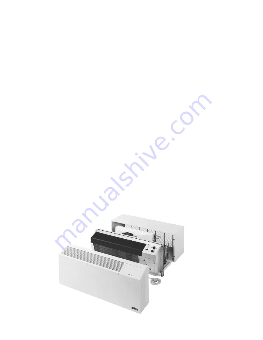
Each conditioner consists of the following components:
1.
Heating/Cooling Chassis & Front Panel.
2.
Cabinet/Wall Sleeve.
3.
Out door Louver-Shipped in a separate carton.
4.
Subbase (not shown) - Optional on all 208V and 230V
heat pump and electric heat units. Standard for all 265V
and hydronic heater option. Shipped in a separate
carton.
5.
Motorized water/steam valve (hydronic only).
6.
Electrical receptacle - 265 volt or hydronic heat.
(Optional for 208/230 volt electric heat.)
7.
Plug cord cover - 265 volt (optional 208/230 volt).
(Not required for hydronic heat)
When the equipment is received all items should be carefully
checked against the bill of lading to be sure all crates and
cartons have been received. All units should be carefully in-
spected for damage when received. If any damage is noticed,
the carrier should make the proper notation on the delivery
receipt acknowledging the damage. The carrier should also
fill out a carrier Inspection Report. The McQuay Inc.Traffic
Department should then be contacted. The unit nameplate
should be checked to make sure the voltage agrees with the
power supply available. The Suite Series Comfort Conditioner
is designed and built for through the-wall installation in either
new or existing buildings. The self-contained refrigerant sys-
tem delivers cooling to the desired space. Heating can be ac-
complished with electric resistance, hydronic or with reverse
Installation ........................................................................... 2
Inspection ........................................................................... 2
Nomenclature ...................................................................... 3
Wall Opening Requirements ............................................... 4
Wall Sleeve Installation
Frame & Brick .............................................................. 5
Panel Wall Construction .............................................. 6
Thick Wall Construction ............................................... 7
Wall Sleeve Extension
Louver Frame ............................................................... 8
Subbase Installation ............................................................ 9
Installation of Optional Condensate Drain Kit ................... 10
Installation of Louvers ....................................................... 11
Table of Contents
Installation
The installation of this equipment shall be in accordance with
the regulations of authorities having jurisdiction and all appli-
cable codes. It is the responsibility of the installer to deter-
mine and follow the applicable codes. Sheet metal parts, self-
Inspection
Figure 1. Exploded View of Complete Unit (Single Motor
Installation of Chassis ....................................................... 11
Adjusting Temperature Limiting Device ............................ 12
Electrical Service ............................................................... 12
Equipment Startup ............................................................ 12
Remote Mounted Thermostat ........................................... 13
Scheduled Maintenance ................................................... 13
Recommended Spare Parts .............................................. 14
Refrigeration Cycle ........................................................... 14
Troubleshooting Chart .................................................. 15/16
Approximate Shipping Weights ........................................ 16
Wiring Diagrams (1-Motor) ................................ 17,18,19, 20
Wiring Diagrams (2-Motor) .............................. 21, 22, 23, 24
Summary of Contents for Suite II
Page 25: ...IM 671 Page 25 of 28 NOTES...
Page 26: ...IM 671 Page 26 of 28 NOTES...
Page 27: ...IM 671 Page 27 of 28 NOTES...


