background image

3

The SART operates by receiving a pulse from the search radar and sending back a
series of pulses in response, which the radar will then display as if they were
normal echoes. The first return pulse, if it sent back immediately, will appear in the
same place on the PPI as a normal echo would have done. Subsequent pulses,
being slightly delayed, appear to the radar like echoes from objects further away. A
series of dots is therefore shown, leading away from the position of the SART. This
distinctive pattern is much easier to spot than a single echo such as from a radar
reflector. Moreover, the fact that the SART is actually a transmitter means that the
return pulses can be as strong as echoes received from much larger objects.

A complication arises from the need for the SART to respond to radars which may
be operating at any frequency within the 9GHz band. The method chosen for the
SART is to use a wideband receiver (which will pick up any radar pulses in the
band), in conjunction with a swept frequency transmitter. Each radar pulse received
by the SART results in a transmission consisting of 12 forward and return sweeps
through the range 9.2GHz to 9.5GHz. The radar will only respond to returns close
to its own frequency of operation (ie. within its receive bandwidth), so a "pulse" is
produced at the radar input each time the SART sweep passes through the correct
frequency.

A slow sweep would give the radar a stronger echo to deal with as the sweep
would be inside the operating bandwidth for a longer period. The delay for the
sweep to reach the operating frequency may however lead to an unacceptable
range error, as delayed echoes appear to be coming from more distant objects.

To minimise this problem, the SART uses a "sawtooth" response, sweeping quickly,
then slowly for each of its twelve forward and return sweeps. At long range, only
the slow sweeps, giving the strongest returns, are picked up

.  

At close range,

where errors are more important, the fast sweeps are also detected. As the first
sweep is a fast one, then the range error is minimised and should be less than 150
metres.

The timescale over which all this occurs is very short. Each "fast" sweep takes
about 0.4

µ

s, each "slow" sweep about 7.5

µ

s. The complete series of twelve

forward and return sweeps is therefore complete within 100

µ

s. Displayed on the

PPI, the spacing between each pair of dots will be 0.6 nautical miles.

On a long range setting, a typical radar will be triggering the SART every
millisecond - but only during the period that the rotating radar scanner is pointing in
the correct direction. Most modern radars use sophisticated noise rejection
techniques, which prevent the display of echoes which are not synchronized with
the radar's own transmissions, so one radar will not normally be confused by a
SART's response to a neighbouring radar.

The SART indicates that it has been triggered by lighting an indicator LED
continuously (it flashes in standby mode) and by sounding an integral buzzer. If no
radar pulses are detected for a period exceeding 15 seconds, the SART reverts to
"standby" mode.

Summary of Contents for S4 Rescue SART

Page 1: ...S4 RESCUE SART Search And Rescue Transponder User Manual ...

Page 2: ...replacement 7 Technical description 8 Function chart 8 Dimensions 9 Operation of marine radar for SART detection 10 Radar Range Scale 10 SART Range Errors 10 Radar Bandwidth 10 Radar Side Lobes 10 Detuning the Radar 10 Gain 10 Anti Clutter Sea Control 11 Anti Clutter Rain Control 11 Technical Specification 12 Declaration of Conformity 13 Limited Product Warranty 15 ...

Page 3: ...vicable parts Return to your dealer for service Dispose of this device safely Contents include Lithium batteries do not incinerate puncture deform or short circuit This device emits radio frequency radiation when activated Because of the levels and duty cycles such radiation is not classed as harmful However it is recommended that you do not hold the radome while the SART is activated The battery ...

Page 4: ...te battery replacement Each SART carries a unique serial number on the label on the orange body LIFERAFT SART Supplied with or without mast Normally is packed as part of the liferaft equipment The mast version is mounted in the same manner as the carry off version the version without the mast is intended to be hung from the highest point inside the liferaft The SART itself is identical with the ca...

Page 5: ... deal with as the sweep would be inside the operating bandwidth for a longer period The delay for the sweep to reach the operating frequency may however lead to an unacceptable range error as delayed echoes appear to be coming from more distant objects To minimise this problem the SART uses a sawtooth response sweeping quickly then slowly for each of its twelve forward and return sweeps At long ra...

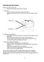
Page 6: ...nting bracket to a bulkhead in a convenient location The recommended fixing is by M5 marine grade stainless steel eg A4 316 bolts length is dependent upon application The bolts should be secured with either stainless steel locking nuts or stainless steel nuts with stainless steel shakeproof washers Mount the SART dome uppermost onto the bracket by locating the lugs on the SART pole mount into the ...

Page 7: ...5 SART General Assembly Ring for internal liferaft mounting Radome Operating switch ring Battery pack Lanyard Mounting pole Bulkhead Mounting bracket Velcro strap omitted for clarity Velcro strap ...

Page 8: ...allow pole sections to drop Lock sections together by twisting each section To deploy in a survival craft liferaft Extend the SART supporting pole as detailed above Tether the SART to a suitable point using the lanyard which unwinds from its base Inset the SART through the port in the canopy Position the bottom of the support pole in the antenna pocket Secure the pole to the canopy support Some su...

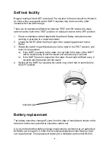
Page 9: ...right to the TEST position and hold it in this position a If the SART responds to the radar the red light in the base of the SART will be continuously lit and the buzzer will sound every 2 seconds b If the SART does not respond to the radar the red light will flash every 2 seconds and the buzzer will not sound 4 Switch off the SART by releasing the switch ring check that it returns fully to the OF...

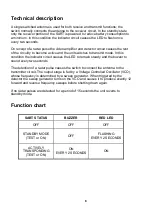
Page 10: ...tion the indicator circuit causes the LED to remain steady and the buzzer to sound every two seconds The detection of a radar pulse causes the switch to connect the antenna to the transmitter circuit The output stage is fed by a Voltage Controlled Oscillator VCO whose frequency is determined by a sweep generator When triggered by the detector the sweep generator turns on the VCO and causes it to p...

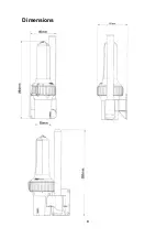
Page 11: ...9 Dimensions ...

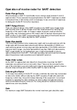
Page 12: ...es on long range and wide bandwidths of 10 25MHz with short pulses on short ranges Any radar bandwidth of less than 5MHz will attenuate the SART signal slightly so it is preferable to use a medium bandwidth to ensure optimum detection of the SART The Radar operating manual should be consulted about the particular radar parameters and bandwidth selection Radar Side Lobes As the SART is approached s...

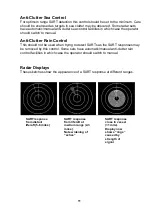
Page 13: ...is should not be used when trying to detect SARTs as the SART responses may be removed by this control Some sets have automatic manual anti clutter rain control facilities in which case the operator should switch to manual Radar Displays These sketches show the appearance of a SART response at different ranges SART response from distant liferaft 5 6 miles SART response from liferaft at medium rang...

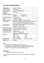
Page 14: ...C to 65 0 C RECOVERY TIME Following excitation 10µs or less ANTENNA HEIGHT Greater or equal to 1m Note 2 RESPONSE DELAY 0 5µs or less ANTENNA BEAM Vertical 12 5 degrees Azimuth Omnidirectional to 2dB WEIGHT SART only 360g SART pole 510g SART complete 530g DIMENSIONS Overall in bracket 283 x 101 x 90mm BUOYANCY Buoyant Note 1 Effective receiver sensitivity includes antenna gain 2 The effective ante...

Page 15: ...13 Declaration of Conformity ...

Page 16: ...14 Declaration of Conformity page 2 ...

Page 17: ...er are not to be affected In order to be valid claims must be made under the above warranty in writing as soon as practicable after discovery of the defect or failure and within the warranty period referred to above Proof of purchase will be required The claim should be sent together with the product in question to the address set out below or to an Approved Service Agent Following a valid warrant...

Page 18: ...16 User Notes ...
Page 19: ...17 This page contains no other data ...

Page 20: ...ver Point Airport Service Road Portsmouth Hampshire United Kingdom PO3 5PB Telephone Int 44 0 23 9262 3900 Fax Int 44 0 23 9262 3998 sales mcmurdo co uk www mcmurdo co uk A member of Chemring Group PLC 86 920 001 Issue 1 ...
Reviews: