background image

11

Caution: Do not connect the AC Power Cord to the 

MA9000 Rear Panel until after the Loudspeaker 

Connections are made. Failure to observe this 

could result in Electric Shock.

The connection instructions below, together with the 

MA9000 Connection Diagram located on the separate 

folded sheet “

Mc2B

”, is an example of a typical audio 

system. Your system may vary from this, however the 

actual components would be connected in a similar 

manner. For additional information refer to “Connec-

tor and Cable Information” on page 3.

The McIntosh MA9000 Power Amplifier Circuitry 

is designed for Loudspeakers with an impedance of 

2 ohms, 4 ohms or 8 ohms. Connect a single Loud-

speaker only to the Right and Left Output Terminals.

When connecting Loudspeakers to the MA9000 

it is very important to use cables of adequate size, so 

there is little to no power loss in the cables. The size is 

specified in Gauge Numbers or AWG (American Wire 

Gauge). The smaller the Gauge number, the larger the 

wire size:

Loudspeaker Cable Distance vs Wire Gauge Guide

Loudspeaker

Impedance

25 feet

(7.62 meters)

or less

50 feet

(15.24 meters)

or less

100 feet

(30.48 meters)

or less

2 Ohms

12AWG

10AWG

8AWG

4 Ohms

14AWG

12AWG

10AWG

8 Ohms

16AWG

14AWG

12AWG

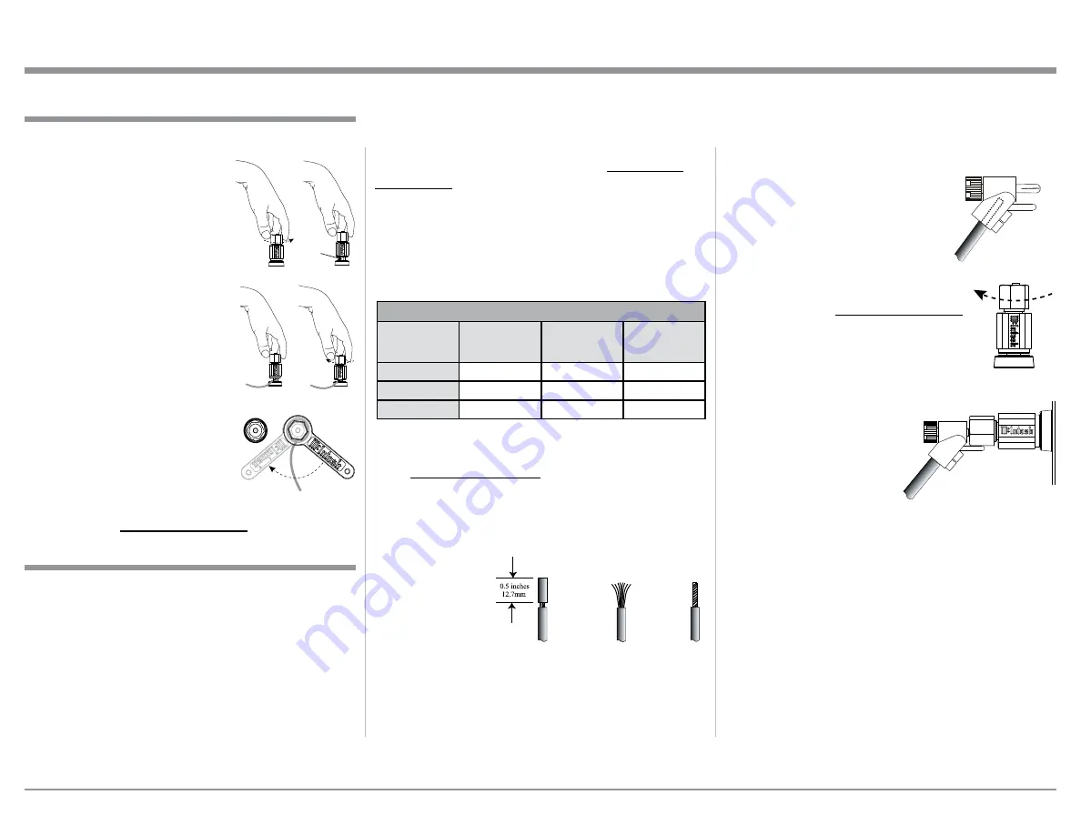
1. Prepare the Loudspeaker Hookup Cable for attach-

ment to the MA9000 Power Amplifier Circuitry:

Bare wire cable ends:

Carefully remove sufficient insulation from the 

cable ends, refer to figures F, G & H. If the cable 

is stranded, carefully twist the strands together 

as tightly as possible.

Notes: 1. If desired, the twisted ends can be tinned 

with solder to keep the strands together.

2. The prepared bare wire cable ends may be 

inserted into spade lug connectors.

3. Banana plugs are for use in the United 

States and Canada only.

Banana Plugs are for use in the United States and 

Canada only:

2. Attach the previously prepared bare wire cable ends 

into the banana plugs and secure 

the connections. Refer to figure I.

3. Rotate the Output Terminal Post 

clockwise until it is finger tight. 

Refer to figure J. Then using the 

McIntosh Wrench, rotate the top 

of the Output Terminal one quarter 

of a turn (90°). 

Do not over tighten.


Refer to figure E.

4. Referring to figure K, connect the 

Loudspeaker hookup cables with 

banana plugs into the hole at the 

top of the terminal to 

the MA9000 Negative 

Output Terminal and 

Positive Output Terminal 

indentified as 2Ω (ohms), 

4Ω (ohms) or 8Ω (ohms) 

connection to match the 

impedance of the Loudspeaker, being careful to 

observe the correct polarities.

Note: The illustration located on the separate 

folded sheet “Mc2B” is for connection to an 

8Ω (ohms) Loudspeaker.

If the Loudspeaker’s impedance is in-between 

the available connections, use the nearest lower 

impedance connection. Refer to “General Informa-

tion” Note 6 on page 3 for additional information.

WARNING: Loudspeaker terminals are hazard-

ous live and present a risk of electric 

shock. For additional instruction on 

making Loudspeaker Connections con-

tact your McIntosh Dealer or McIn-

tosh Technical Support.

Output Terminals

When connecting the Loudspeaker Hookup Cables to 

the MA9000 Amplifier Output Terminals please fol-

low the steps below:

1. Rotate the top of the Output 

Terminal Post counterclock-

wise until an opening appears. 

Refer to figures A and B.

2. Insert the Loudspeaker 

hookup cable into the Output 

Terminal Post opening or the 

cable spade lug around the 

center post of the Output Ter-

minal. Refer to figure C.

3. Rotate the top of the Output 

Terminal Post clockwise 

until it is finger tight. Refer to 

figure D.

4. Place the supplied McIntosh 

Wrench over the top of the 

Output Terminal and rotate it 

one quarter of a turn (90°) to 

secure the Loudspeaker Cable 

Connection. 

Do not over tighten.

 Refer to figure E.

How to Connect Loudspeakers

Figure F 

Figure G

Figure H

Figure I

Figure A

Opening

Figure B

Figure C

Figure D

Figure E

Figure J

Figure I

Figure K

Summary of Contents for MA9000

Page 1: ...McIntosh Laboratory Inc 2 Chambers Street Binghamton New York 13903 2699 Phone 607 723 3512 www mcintoshlabs com MA9000 Integrated Amplifier Owner s Manual...

Page 2: ..._____________________ Purchase Date ________________________________ Dealer Name _________________________________ Important Safety Information is supplied in a separate document Important Additional...

Page 3: ...the MA9000 has activated the Front Panel Power Guard LEDs are illuminated continuously and the sound will be muted 5 When the Power Transformer has overheated due to improper ventilation and or high...

Page 4: ...t resolution decodes up to DSD256 Digital Signals and DXD 24 Bit with a sampling rate up to 384kHz Moving Coil and Moving Magnet Phono Inputs The MA9000 has two precision Phono Preamplifier Circuits f...

Page 5: ...on the next page pertaining to installing the MA9000 into cabinets Front View of the MA9000 Rear View of the MA9000 Side View of the MA9000 17 1 2 44 5cm 3 16 0 5cm 16 13 16 42 7cm 7 8 2 2cm 7 15 16 7...

Page 6: ...ntaining all the system components at the coolest possible operating temperature A custom cabinet installation should provide the following minimum spacing dimensions for cool operation Allow at least...

Page 7: ...of Rear Panel Connections for the MA9000 Integrated Amplifier is located on a separate folded sheet contained in the Owner s Manual Packet Refer to separate sheet Mc1A for the Rear Panel Connections...

Page 8: ...ect a Control Cable from the MA9000 DATA PORT Jack 2 to the AM FM Tuner Data In Jack 10 Connect a Control Cable from the MA9000 Jack 1 to the Media Server Data In Jack 11 Connect any additional McInto...

Page 9: ...input 1 Connect Audio Cables from the A V Processor FL Front Left and FR Front Right Channel Outputs to the MA9000 UNBALANCED Num ber 6 INPUTS Left and Right Jacks 2 Connect a Control Cable from the...

Page 10: ...Jumpers from between the OUTPUT 1 Jacks and the PWR AMP In Jacks located on the Rear Panel of the MA9000 Note Place the McIntosh Jumper in a safe place for possible future use 2 Using a pair of shield...

Page 11: ...sly prepared bare wire cable ends into the banana plugs and secure the connections Refer to figure I 3 Rotate the Output Terminal Post clockwise until it is finger tight Refer to figure J Then using t...

Page 12: ...ly clamped into the terminals so the lugs or wire cannot slip out Refer to figures L and M Note The illustration located on the separate folded sheet Mc2B is for connection to an 8 ohms Loudspeaker If...

Page 13: ...13...

Page 14: ...used with McIntosh Models displaying instructions on a video screen Press to change Broadcast BANDs on a connected Tuner Select certain functions on a variety of McIntosh Models Select the DEVICE to...

Page 15: ...ation on assigning the Data Ports refer to Data Ports on page 20 Trim Press the TRIM Push button until the desired Trim function Balance Trim Level etc appears on the MA9000 Front Panel Display then p...

Page 16: ...1 and 2 On or Off INFORMATION DISPLAY indicates the Sources Volume other Audio Settings Operational Functions and Setup Mode Settings EQUALIZER Push button with indicator when deactivated the audio s...

Page 17: ...ny time by How to Operate the Setup Mode The Default Settings Chart below indicates the Func tion Name Default Setting and the Page Number for additional information Default Settings Firmware Version...

Page 18: ...in the INPUT Control until SET UP BAL On Rename appears on the Display If necessary rotate the INPUT Control to select the BAL Input Refer to figure 8 14 Press and hold in the INPUT Control until RE...

Page 19: ...old in the INPUT Control until SETUP OUTPUT 1 Switched appears on the Display Refer to figure 20 4 Rotate the VOLUME ADJUST Control to change from the Switched setting to Unswitched Refer to figure 21...

Page 20: ...rom the available additional selections including Output 2 or Input Refer to figure 28 5 In a similar manner perform steps 3 and 4 to change the Trigger 2 setting from OUTPUT 2 to Main Refer to figure...

Page 21: ...nges PCM DSD etc On occasion due to the way a Digtal Audio Music Recording was made it may become desirable to switch Off the USB Automute Feature To switch Off Automute perform the following steps 1...

Page 22: ...tion Dis play Refer to figure 43 3 Rotate the VOLUME ADJUST Control to select Disabled Refer to figure 44 5 Exit the SETUP Mode by several presses of the INPUT Control Figure 43 SETUP Front IR Enabled...

Page 23: ...Front Panel STAND BY Push button to switch On the MA9000 Figure 49 FACTORY RESET Completed Figure 47 FACTORY RESET Hold INPUT Figure 48 FACTORY RESET In Progress Reset of Microprocessors In the unlik...

Page 24: ...es 50 51 52 and 53 To switch OFF the MA9000 press the STANDBY ON Push button on the Front Panel or the Power Red Push button on the Remote Control Trim Functions The MA9000 has various Trim Selections...

Page 25: ...formation Display returns to indicate the Source Selection and Volume Level TRIM LEVEL Source Components can have slightly different volume levels resulting in the need to readjust the MA9000 Volume C...

Page 26: ...O STEREO MODE By default the Stereo Mode is active for all Input Sources however any Input Source may be assigned to Mono Mode To change Stereo Mode to Mono for a given Input Source perform the follow...

Page 27: ...he push button will extinguish Note 1 The audio signal present at the FIXED OUTPUT Jacks is unaffected by the Equalizer Circuitry 2 The EQUALIZER can also be accessed by the TRIM Function refer to pag...

Page 28: ...BALANCE or EQUALIZER Controls Setting Using a Separate Power Amplifier There are two different ways to use a separate power amplifier with a MA9000 The first way is to use the separate amplifier inste...

Page 29: ...centered at the frequency marked above the controls The center frequencies of these controls are at 25Hz 50Hz 100Hz 200Hz 400Hz 1 000Hz 2 500Hz and 10 000Hz Both Left and Right Channels are affected...

Page 30: ...v1 0 and download the PC Windows Driver Follow the instruc tions below to install the McIntosh MA9000 Driver Purpose To Install the McIntosh USB Audio Windows Driver for use with McIntosh Products wi...

Page 31: ...tosh HD HS USB Audio and than click on the Set Default button Notes 1 When the McIn tosh USB Audio Product is not connected to your computer the previous default Audio Device will be selected 2 If oth...

Page 32: ...the Application Output Format when available and the McIntosh HD Control Panel Settings Note In general when the original music is recorded at a higher Sampling Rate the result is usually more detail...

Page 33: ...33 Photos...

Page 34: ...34...

Page 35: ...35 Photos...

Page 36: ...98dB below rated output Phono MM 84dB below 5mV input Phono MC 82dB below 0 5mV input Input Impedance High Level 22K ohms Unbalanced 44k ohms Balanced Phono MM 50 to 400pF in 50pF steps 47K ohms Phon...

Page 37: ...Power Guard Less than 2 THD with up to 16dB overdrive at 1 000Hz Frequency Response 0 0 25dB from 20Hz to 20 000Hz 0 3 0dB from 10Hz to 100 000Hz Input Sensitivity for rated output 1 7 Volts Signal To...

Page 38: ...60Hz at 3 6 amps 230 Volts 50 60Hz at 3 3 amps 240 Volts 50 60Hz at 3 3 amps Standby Less than 0 25 watt Note Refer to the rear panel of the MA9000 for the cor rect voltage Overall Dimensions Width is...

Page 39: ...the original shipping carton and interior parts only if they are all in good serviceable condition If a shipping carton or any of the interior part s are needed please call or write Customer Service D...

Page 40: ...cts is the policy of McIntosh Laboratory Incorporated who reserve the right to improve design without notice Printed in the U S A McIntosh Laboratory Inc 2 Chambers Street Binghamton NY 13903 www mcin...

Reviews: