background image

9 - 1

Hydraulic Fluids

Hydraulic Fluids

The use of proper hydraulic fluid is mandatory to achieve maximum performance and machine life. Use a clean, high 

quality, anti-wear hydraulic fluid with a viscosity index (VI) of 135 minimum. It should have a maximum viscosity of 

500 cSt (2000 SSU) at startup (ambient temperature) and a minimum viscosity of 13 cSt (65 SSU) at the maximum 

fluid temperature (generally 80

°

F above ambient). Using hydraulic fluids that do not meet these criteria may cause 

poor operation and/or damage to the hydraulic components.
The following table specifies the fluid temperature at various viscosities. Temperature rise of the hydraulic fluid 

can vary from 30

°

 F to about 80

°

 F over the ambient temperature depending on the pressure setting, age of the 

pump, wind, etc. Mobil Univis N46 hydraulic fluid is installed at our factory. The advantage of this fluid is a wider 

temperature range, however, this fluid should not be used for continuous operation below 24

°

F. 

TX03082-04-18-16

NOTE: This chart is based on pump manufacturer recommendations of 13 to 500 cSt.
NOTE: Temperatures shown are fluid temperatures. – NOT ambient temperatures.

Hydraulic Fluids Characteristics

Manufacturer Fluid 

Name 

cSt  cSt V.I. -20F 

-10F  0F  10F  30F  50F  70F  90F  110F  130F 150F 

Range  Range


  100F 

210F 


°

°

C


Mobil 

DTE 10 Excel 15  15.8  4.1  168       *********************************************** 


-16 - 113  -27 - 45


DTE 10 Excel 32  32.7  6.6  164                                  ********************************************* 

12 - 154  -11 - 68


DTE 10 Excel 46  45.6  8.5  164                                       ********************************************* 

23-173  -5 - 78


DTE 10 Excel 68  68.4  11.2  156                                               *******************************************  37-196  3 - 91


Univis N-32 

34.9  6.9  164                                  ******************************************** 

12-150  -11 - 66


Univis N-46 

46  8.5  163                                       ******************************************** 

24-166  -4 - 74


Univis N-68 

73.8  12.1  160                                                  *****************************************  39-193  4 - 89

Summary of Contents for DynaMc 250HP

Page 1: ...Manual 1270901 Revision E 10 18 28 250 and 412 Hand Pump Fusion Machines Operator s Manual Original Language English...

Page 2: ...oduct and other products could be protected by patents or have patents pending All the latest patent information is available at patent mcelroy com Cancer and Reproductive Harm www P65warnings ca gov...

Page 3: ...ore than 30 years McElroy has been the only pipe fusion machine manufacturer to continuously offer advanced training Course offerings are meant to enhance your efficiency productivity and safety in th...

Page 4: ...Fulton Street Tulsa Oklahoma 74158 0550 PHONE 918 836 8611 FAX 918 831 9285 EMAIL fusion McElroy com Note Certain repairs warranty work and inquiries may be directed at McElroy s discretion to an aut...

Page 5: ...y of Heat Fusion 2 1 Introduction to the DynaMc 28 250 and 412 Hand Pump Fusion Machine 2 2 Carriage Assembly 2 2 Oil Reservoir 2 3 Pump 2 3 Hydraulic Cylinders 2 3 Facer 2 4 Heater 2 5 Heater Strippe...

Page 6: ...6 Check Heater Temperature 3 6 Inserting Heater 3 7 Heating the Pipe 3 7 Fusing the Pipe 3 8 Opening Movable Jaws 3 8 Opening Fixed Jaws 3 9 Position Pipe for Next Joint 3 9 Install Next Piece of Pip...

Page 7: ...Facer 6 3 Facer Blades 6 3 Clean Heater Surfaces 6 4 Installing Butt Fusion Heater Plates 6 4 Adjusting Heater Temperature 6 4 Heater Indicator Light 6 5 Bleeding Air From Hydraulic System 6 5 Machin...

Page 8: ...actices IMPORTANT can help you do a better job or make your job easier in some way PELIGRO Read and Understand Do not operate this equipment until you have carefully read and understand all the sectio...

Page 9: ...afe SAFE1ST 1 2 22 92 Wear Safety Equipment Wear a hard hat safety shoes safety glasses and other applicable personal protective equipment Remove jewelry and rings and do not wear loose fitting clothi...

Page 10: ...ommended that the pipe is always held securely by either being clamped in the fusion machine jaws or properly attached to a lifting device NOTICE Do not leave machine unattended to unauthorized person...

Page 11: ...perated equipment it is important to remember that a sudden hydraulic oil leak can cause serious injury or even be fatal if the pressure is high enough Escaping fluid under pressure can penetrate the...

Page 12: ...CE Disconnect power from the facer and remove the facer blades before attempting any maintenance or adjustment NOTICE Never extend the blade beyond the inner or outer circumference of the facer TX0237...

Page 13: ...eak tight connection is the result The principal operations include Clamping The pipe pieces are held axially and radially to allow all subsequent operations to take place Facing The pipe ends are fac...

Page 14: ...ssemblies have a hydraulic hand pump to pressure the hydraulic cylinders to move the jaws TX02949 4 15 09 Overview Introduction to the DynaMc 28 250 and 412 Hand Pump Fusion Machine The McElroy DynaMc...

Page 15: ...fer to the Check Hydraulic Fluid Level section for instructions on checking and filling the hydraulic fluid Refer to the Hydraulic Fluids section of this manual for hydraulic fluid recommendations TX0...

Page 16: ...s of the motor Both brushes must be removed A 1 1 8 hex shaft allows for manual operation in hazardous conditions Remove brushes on the Eibenstock facer motor The armature brushes must be removed from...

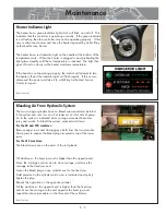
Page 17: ...dicator is not flashing then the controller may not be operating properly If this occurs disconnect power and have the heater repaired by a McElroy Authorized Service Center The heater temperature is...

Page 18: ...r Stand The heater should always be stored in the insulated heater stand or blanket for protection of the operator and to minimize heat loss and risk of mechanical damage TX00363 9 15 94 PH03874 4 15...

Page 19: ...Procedure STOP 12 22 92 3 1 Prepare Heater Heater is not explosion proof Operation of heater in an explosive atmosphere without necessary safety precautions will result in serious injury or death If...

Page 20: ...atch the size of the jaw without inserts TX02956 4 15 09 PH00304 9 24 93 Pump Use the carriage control valve to select desired carriage direction The neutral position does not apply pressure to the cy...

Page 21: ...Jaw Configuration The DynaMc HP 4 jaw machines can be configured to a 2 movable jaw 2 fixed jaw configuration or a 3 movable jaw 1 fixed jaw configuration This will allow work in close proximity to e...

Page 22: ...bottoms out on facer stops Allow the facer to run for several revolutions to ensure that there are no chips hanging to the end of the pipe Turn facer off TX02960 4 15 09 Loading Pipe Into Machine Cle...

Page 23: ...rea If pipe is not lined up tighten the high side jaw to bring into alignment IMPORTANT Always tighten the side that is higher never loosen the low side When the pipe is properly aligned tighten outsi...

Page 24: ...ater surface temperature Refer to the pipe manufacturer s recommendations for proper heater temperature IMPORTANT The dial thermometer on the heater indicates internal temperature which varies from th...

Page 25: ...may be necessary to omit Step C to prevent the pipe from pulling away from the heater If this is necessary drag pressure must be manually maintained by actuating the pump lever TX02963 4 15 09 Insert...

Page 26: ...engage the stripper bar Quickly remove the heater C Shift carriage control valve to close carriage Quickly move the carriage to the left bringing the pipe ends together under the pipe manufacturer s r...

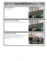
Page 27: ...Opening Fixed Jaws Open the fixed jaws TX00381 9 16 94 PH03891 4 15 09 PH03891 4 15 09 Install Next Piece of Pipe Move the carriage control valve to the open position and actuate the pump lever to op...

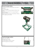
Page 28: ...ed from the base for close quarters in ditch fusion To remove the carriage Remove one of the nuts from the threaded rod at the base of the carriage Remove the threaded rod out of the carriage and thro...

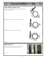
Page 29: ...nder pipe Rotate carriage assembly around to a normal upright position Attach the top jaws and loosely clamp around pipe TX00879 2 19 96 CD00193c 2 19 96 CD00194c 2 19 96 CD00195c 2 19 96 Make Fusion...

Page 30: ...with valve system facing up to protect against damage Attach upper jaws to carriage Tighten clamp knobs Attach sling to carriage Lift carriage assembly from ditch TX02969 4 27 09 Reassemble Fusion Mac...

Page 31: ...ety warnings 1 Do not exceed rated load or lift loads greater than the rated load rating of the lifting device 2 Do not operate a damaged or malfunctioning lifting device 3 Do not lift persons 4 Do no...

Page 32: ...or lifting equipment of proper lifting capacity to lift the machine Tighten the jaw clamp knobs Attach a properly rated lifting sling through the center of all four jaws Using proper overhead rigging...

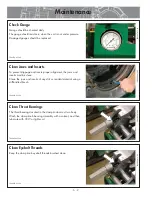
Page 33: ...evel should be checked daily The reservoir should be approximately half full of fluid Do not overfill If the pump and cylinders are empty fill pump with fluid and move the carriage left and right full...

Page 34: ...rial using a stiff bristled brush TX00433 9 15 94 Clean Thrust Bearings The thrust bearings located in the clamp knobs must turn freely Wash the clamp knob bearing assembly with a solvent and then lub...

Page 35: ...st be replaced NOTICE Never extend the blade beyond the inner or outer circumference of the facer TX02475 3 29 05 Fasteners Must Be Tight Check all nuts bolts and snap rings to make certain they are s...

Page 36: ...t the butt fusion heater plates are seated on the heater body and that there is no foreign matter trapped between these surfaces IMPORTANT Do not over tighten the bolts The surface of the butt fusion...

Page 37: ...opposite end is higher than the fixed jaw end Move the carriage to the end opposite the fixed jaw and repeat the above procedure on the this end of the cylinders TX02975 4 15 09 PH03872 4 15 09 Maint...

Page 38: ...is on the basic machine Hydraulic pump is filled to correct level Machine is free of hydraulic leaks Hydraulic gauge reads correctly Jaws are properly aligned Facer operates smoothly Face off is squa...

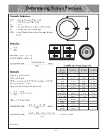
Page 39: ...PS SDR 11 O D 8 625 inch DRAG as measured in PSI for this example use 30 PSI Recommended IFP 75 PSI Using a Model 28 High Force Fusion Unit O D 8 625 t 0 784 SDR 11 TEPA 4 71 From Table O D t t IFP GA...

Page 40: ...80 F over the ambient temperature depending on the pressure setting age of the pump wind etc Mobil Univis N46 hydraulic fluid is installed at our factory The advantage of this fluid is a wider temper...

Page 41: ...7 kg Heater 28 21 lbs 9 5 kg 250 27 lbs 12 2 kg 4 Jaw DynaMc 28 HP 250 HP Width 25 9 658mm Length 34 3 872mm Height 23 4 595mm Weight 155 lbs 70 kg without cradle 142 lbs 64 kg Facer 39 lbs 17 7 kg He...

Page 42: ...9 kg 4 Jaw DynaMc 412 HP Width 31 7 805mm Length 34 7 882mm Height 26 5 673mm Weight 293 lbs 132 kg without cradle 277 lbs 125 kg Facer 54 lbs 24 5 kg Heater 24 lbs 10 9 kg Specifications Maximum Pre...

Page 43: ...his manual is waterproof tear resistant grease resistant abrasion resistant and the bonding quality of the printing ensures a readable durable product The material does not contain any cellulose based...

Page 44: ......

Reviews: