background image

6000XL Series Service and Installation Manual

For customer service, call (800) 733-8829, (800) 733-8821, Fax (888) 779-2040, www.delfield.com

6

Delfield

®

Stabilizing

Some models are supplied on casters for your convenience, 

ease of cleaning underneath and for mobility. It is very 

important, however, that the cabinet be installed in a stable 

condition with the front wheels locked while in use.

Should it become necessary to lay the unit on its side or back 

for any reason, allow at least 24 hours before start-up so as 

to allow compressor oil to flow back to the sump.  Failure to 

meet this requirement can cause compressor failure and unit 

damage.

Unit repairs will not be subject to standard unit 

warranties due to improper installation procedures. 

Electrical connection

Refer to the amperage data on the specifications page, the 

serial tag, your local code or the National Electrical Code to 

be sure the unit is connected to the proper power source. A 

protected circuit of the correct voltage and amperage must be 

run for con nec tion of the line cord, or permanent connection 

to the unit.

The thermostat must be turned to OFF and the unit 

disconnected from the power source whenever 

performing service, maintenance functions or 

cleaning the refrigerated area.

Power Switch

Select units are equipped with a power disconnect switch 

located next to the energy saver switch and thermostat control 

knob. Switch must be in the “on” position for the unit to 

operate. On freezers, if the switch is turned off, then returned 

to the on position, the unit will enter a defrost cycle and the 

display will read “Def.”

Upon powering unit, there could be up to a 10 

minute delay before unit begins to cool.

Installation

Location

Units represented in this manual are intended for indoor use 

only.   Be sure the location chosen has a floor strong enough 

to support the total weight of the cabinet and contents. A fully 

loaded 6000XL series can weigh as much as 1500 pounds. 

Reinforce the floor as necessary to provide for maximum 

loading.  For the most efficient refrigeration, be sure to provide 

good air circulation inside and out.

Inside cabinet:

 Do not pack refrigerator so full that air cannot 

circulate.  The refrigerated air is discharged at the top rear of 

the unit.  It is important to allow for proper air flow from the 

top rear to the bottom of the unit.  Obstructions to this air flow 

can cause evaporator coil freeze ups and loss of temperature 

or overflow of water from the evaporator drain pan.  The rear 

of the unit has molded ribs and the shelves have a rear turn 

up on them to prevent this.  However, 

bags and other items can still be 

located to the far rear of the cabinet.  

There is also a return air diffuser 

along the top front of the cabinet 

interior, this also requires proper air 

circulation.  Prevent obstruction by 

locating large boxes and tall stacks of 

product to the bottom of the cabinet.  

Outside cabinet:

 Be sure that the 

unit has access to ample air. Avoid 

hot corners and locations near stoves 

and ovens.

It is recommended that the unit be installed no closer than 

2” from any wall with at least 12” of clear space above the 

unit. Avoid exposing glass door units to direct sunlight. Direct 

sunlight through the glass doors will make the ABS liner 

fade and become brittle and will greatly reduce refrigeration 

efficiency.

Leveling

A level cabinet looks better and will perform better because 

the doors will line up with the frames properly, the cabinet will 

not be subject to undue strain and the contents of the cabinet 

will not move around on the shelves. Use a level to make sure 

the unit is level from front to back and side to side.  Units 

supplied with legs will have adjustable bullet feet to make the 

necessary adjustments.  If the unit is supplied with casters, no 

adjustments are available.  Ensure the floor where the unit is 

to be located is level.

Summary of Contents for 6000XL

Page 1: ...s of 95 F 35 C Doing so will cause damage to the unit s Printed in July 2013 Printed in The United States of America 6000XL The Delfield Company Models 6000XL 6100XL Operation Manual Manufactured excl...

Page 2: ...s Not Intended For Use By Persons Who Lack Experience Or Knowledge Unless They Have Been Given Supervision Or Instruction Concerning Use Of The Appliance By A Person Responsible For Their Safety WARNI...

Page 3: ...so the equipment is not damaged while being moved into the building 1 Visually inspect the exterior of the package and skid or container Any damage should be noted and reported to the delivering carri...

Page 4: ...com This manual covers standard units only If you have a custom unit consult the customer service department at the number listed below 2013 The Delfield Company All rights reserved Reproduction with...

Page 5: ...2092 2488 20 F 12 5 12 5 774lbs 351kg 5 20p 6125XL S SH 115 9 0 20 0 15 1 1 2 2092 20 F 12 5 274lbs 124kg 5 15p 6151XL S SH 115 12 0 43 5 33 2 3 4 1923 20 F 12 5 454lbs 206kg 5 15p 6176XL S SH 120 20...

Page 6: ...o support the total weight of the cabinet and contents A fully loaded 6000XL series can weigh as much as 1500 pounds Reinforce the floor as necessary to provide for maximum loading For the most effici...

Page 7: ...by pulling straight up then rotating the cam 180 and pushing back into the hinge 9 Remount the door and check for proper closure and gasket seal Adjust hinges as needed Once adjustment is verified re...

Page 8: ...ed panel on the left side It is factory set at mid range to maintain about 38 F 3 C box temperature To adjust for colder temperatures turn the knob clockwise For warmer temperatures turn the knob coun...

Page 9: ...he coil Freezer Manual Defrost If a manual defrost is desired simply unplug the unit for several seconds then plug unit back in This will cause the control to re initialize and then enter a defrost cy...

Page 10: ...extremely dirty a commercially available condenser cleaner may be required Stainless Steel Care and Cleaning To prevent discoloration or rust on stainless steel several important steps need to be tak...

Page 11: ...aporator coil and evaporates it at an external condensate evaporator pan Each drain can become loose or disconnected from moving or bumping the drain If you notice excessive water accumulation on the...

Page 12: ...sible risk of personal injury Equipment alerts Look for this icon to find information about how to avoid damaging the equipment while doing a procedure Tips Look for this icon to find helpful tips abo...

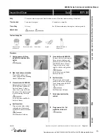
Page 13: ...ducts from inside unit to walk in 2 Wear hand and eye protection Wear rubber gloves and safety goggles when handling cleaner and sanitizer 3 Clean exterior with EXCEED Spray exterior surfaces with EXC...

Page 14: ...Q1 Why In order to maintain proper refrigeration performance the condenser must be clean Time required 5 minutes to prepare 15 minutes to complete Time of day At close For 24 hour restaurants during...

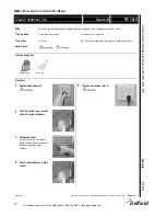
Page 15: ...seal the door to the unit Time required 0 minutes to prepare 10 minutes to complete Time of day At close For 24 hour restaurants during low volume periods Hazard icons None Tools and supplies None Pr...

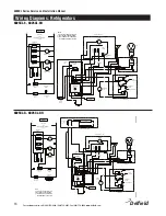
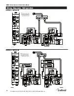
Page 16: ...7 MAY 2011 ADDED L 2 3 DESIGNATION H 4 FOR HEATERTERMINAL 2 3 BROWN COMPRESSORWIREWAS BLACK ON DIAGRAM ONLY 26 MAY 2011 L ENNIS DESCRIPTION SIZE C SCALE UNLESS OTHERWISE SPECIFIED X XX XXX ANG BROKEN...

Page 17: ...TECTOR COMPRESSOR COMPRESSOR WINDING W IN D IN G R U N 14 12 STAR 10 13 11 CAPACITOR START RELAY START BLK BLK M CONDENSER FAN MOTOR 02 MAY 2011 NOTES 1 STRIP TAC ADHESIVE BACKING 2 BLACK PRINT ONWHIT...

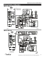
Page 18: ...REWAS BLACK ON DIAGRAM ONLY 3 REVISIONS LOCATION DIMENSIONS ARE IN INCHES TOLERANCES ALL PARTSTO BE DEBURRED AND EDGES UNLESS OTHERWISE SPECIFIED THIRD ANGLE PROJECTION The contents of this document a...

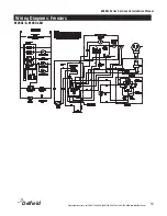
Page 19: ...6000XL Series Service and Installation Manual 19 For customer service call 800 733 8829 800 733 8821 Fax 888 779 2040 www delfield com Delfield Wiring Diagrams Freezers 6125XL S 6125XL SH...

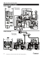
Page 20: ...FAN CONDENSER BLK 1 2 2 1 START WINDING L N L N EVAPORATOR HOUSING LINEVOLTAGE 115 208 230 60 1 SEE NAMEPLATE FOR MAXIMUM FUSE SIZE DEFROST HEATER EVAPORATOR FAN CIRCUIT COMPRESSOR RELAY 1 1 2 32 1 2...

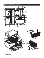
Page 21: ...allation Manual 21 For customer service call 800 733 8829 800 733 8821 Fax 888 779 2040 www delfield com Delfield Refrigeration Package Diagram 4 3 2 9 6 5 1 11 13 14 15 16 17 18 21 7 5 6 1 9 4 14 11...

Page 22: ...9 2194785 2194967 Heater defrost 20 9321629 Clip defrost heater mounting 21 2194953 Switch defrost safety high limit 1702795 Condensate pan 3516041 Solenoid valve used on remote units Refrigerator 2 s...

Page 23: ...l Door s s hinged right edge mount hinges 000 AB9 013P Half Door s s bottom left edge mount hinges 000 AB9 013R Half Door s s bottom right edge mount hinges 000 AB9 013M Half Door s s top left edge mo...

Page 24: ...reimbursed under warranty unless pre approved with a Service Work Authorization from Delfield You must submit the number with the service claim LABOR OF 1 HOUR IS ALLOWED TO REPLACE Thermostat Door Ja...

Page 25: ...6000XL Series Service and Installation Manual 25 For customer service call 800 733 8829 800 733 8821 Fax 888 779 2040 www delfield com Delfield Notes...

Page 26: ...6000XL Series Service and Installation Manual For customer service call 800 733 8829 800 733 8821 Fax 888 779 2040 www delfield com 26 Delfield Notes...

Page 27: ...6000XL Series Service and Installation Manual 27 For customer service call 800 733 8829 800 733 8821 Fax 888 779 2040 www delfield com Delfield Notes...

Page 28: ...D 07 13 9294284 Delfield Thank you for choosing Delfield Help is a phone call away Help our team of professional courteous customer service reps by having your model number and serial number available...

Reviews: