background image

Physical description of the M-1250/M-1450 Sensor

The M-1250/M-1450 Sensor is equipped with eight Fast Ethernet ports (or interfaces). M-1250 can monitor up to

100 Mbps, and M-1450 can monitor upto 200 Mbps of aggregated traffic respectively. The M-1250/M-1450

Sensor can monitor four 10/100/1000 Mbps Ethernet segments in full-duplex mode (tap or in-line), and eight

segments in half-duplex mode (monitoring SPAN ports or hubs).

Ports on the Sensor

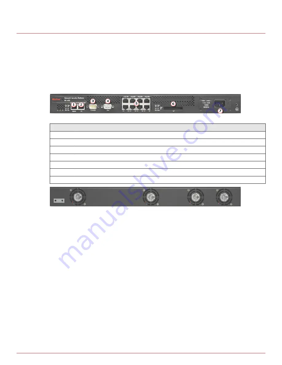
The M-1250/M-1450 Sensor is a one rack-unit (1RU) box equipped with the following ports:

Figure 1-1  M-1450 Sensor Front Panel

Item

Description

1

RJ-45 10/100/1000 Management port (1)

2

RJ-45 Response port (1)

3

RS-232C Console port (1)

4

RS-232C Auxiliary port (1)

5

RJ-45 10/100/1000 Ethernet Monitoring ports (8)

6

External Compact Flash port (1)

7

Power supply A (1)

Figure 1-2  M 1450 Sensor back panel

1

One 10/100/1000 Management port, which is used for secure communication with the Manager server.

Communication between the Sensor and the Manager server uses secure channels; these channels provide

link privacy using encryption and mutual authentication between Sensors and the Manager using public key

authentication. You assign an IP address to this Ethernet port during installation.

2

One Response port, which, when you are operating in the SPAN mode, enable you to inject response

packets back into your network, for example, through a switch or router. The Response port is also used in

the tap mode.

3

One RS-232C Console port, which is used to set up and configure the Sensor.

4

One RS-232C Auxiliary port, which may be used to dial in remotely to set up and configure the Sensor.

5

Eight 10/100/1000 Monitoring ports, which enable you to monitor eight SPAN ports or four full-duplex

tapped segments or four segments in-line. When the Sensor operates in the IPS mode, these ports operate

in stealth mode; that is, they have no IP addresses nor even a TCP/IP stack to respond to IPS detection

techniques. This renders them completely invisible to intruders. When operating in the NAC mode, the

monitoring ports can be assigned IP addresses. The monitoring ports for M-1250/M-1450 Sensor are 1A/1B,

2A/2B, 3A/3B and 4A/4B.

1

Introducing Network Security Sensors

Physical description of the M-1250/M-1450 Sensor

8

McAfee

®

 Network Security Platform

 M-1250/M-1450 Sensor Product Guide

Summary of Contents for M-1250 - Network Security Platform

Page 1: ...M 1250 M 1450 Sensor Product Guide Revision D McAfee Network Security Platform...

Page 2: ...GAL AGREEMENT CORRESPONDING TO THE LICENSE YOU PURCHASED WHICH SETS FORTH THE GENERAL TERMS AND CONDITIONS FOR THE USE OF THE LICENSED SOFTWARE IF YOU DO NOT KNOW WHICH TYPE OF LICENSE YOU HAVE ACQUIR...

Page 3: ...the chassis 15 Mount the Sensor on a rack 16 Cable the Sensor 17 Power on the Sensor 17 Power off the Sensor 17 4 Attaching cables to the Sensor 19 Cable the Console port 19 Cable the Auxiliary port 2...

Page 4: ...B Regulatory compliance and safety information 27 Index 29 Contents 4 McAfee Network Security Platform M 1250 M 1450 Sensor Product Guide...

Page 5: ...cess some or all of its features Conventions This guide uses these typographical conventions and icons Italic Title of a book chapter or topic a new term emphasis Bold Text that is emphasized Monospac...

Page 6: ...find information about a released product including product documentation technical articles and more Task 1 Go to the ServicePortal at https support mcafee com and click the Knowledge Center tab 2 I...

Page 7: ...s About the M 1250 M 1450 Sensor Physical description of the M 1250 M 1450 Sensor About the M 1250 M 1450 Sensor The M 1250 or the M 1450 Sensor provides effective network IPS functionality as well as...

Page 8: ...ncryption and mutual authentication between Sensors and the Manager using public key authentication You assign an IP address to this Ethernet port during installation 2 One Response port which when yo...

Page 9: ...ational M 1250 M 1450 front panel LEDs Figure 1 3 LEDs on the front panel that are used during normal operating conditions Region in the image LEDs represented here 1 Pwr Sys Temp Fan Management Port...

Page 10: ...Figure 1 4 LEDs on the front panel that indicate normal bypass status These LEDs are used during both Inline Fail open and Inline Fail close modes of operation However they also remain green when the...

Page 11: ...hardware or software in the Sensor appliance that is not part of the normal operation of McAfee Network Security Platform Safety measures Please read the following warnings before you install the pro...

Page 12: ...ial environment This equipment generates uses and can radiate radio frequency energy and if not installed and used in accordance with the instruction manual may cause harmful interference to radio com...

Page 13: ...in case you need to move or ship the Sensor If any of the contents from the preceding list are missing or damaged contact McAfee support See also Contents of the Sensor box on page 12 Before you inst...

Page 14: ...2 Before you install Unpack the Sensor 14 McAfee Network Security Platform M 1250 M 1450 Sensor Product Guide...

Page 15: ...e Sensor on page 17 Position the Sensor Place the Sensor in a physically secure location close to the switches or routers it will be monitoring Ideally the Sensor should be located within a standard c...

Page 16: ...should have access to the front and rear of the Sensor Before you mount the Sensor in the rack make sure that power is OFF Remove the power cable and all network interface cables from the Sensor Rack...

Page 17: ...in Installing a power supply For true redundant operation with the optional redundant power supply McAfee recommends that you plug each supply into a different power circuit Task 1 Connect the power c...

Page 18: ...3 Setting up the Sensor Power on the Sensor 18 McAfee Network Security Platform M 1250 M 1450 Sensor Product Guide...

Page 19: ...cations is mentioned as Cat 5 Cat 5e Contents Cable the Console port Cable the Auxiliary port Connect the cable to the Response port Cable the Management port Cable Monitoring ports Cable the Sensor t...

Page 20: ...connections plug a straight through modem cable into the Auxiliary port on the Sensor This port is labeled as Aux on the Sensor front panel 2 Connect a modem to the Aux port 3 Connect a telephone line...

Page 21: ...interconnect the Sensors and the Manager Cable Monitoring ports Monitoring ports connect to the network devices you will be monitoring using the Sensor You can deploy Sensors in the following operatin...

Page 22: ...negotiation is ON Speed is configurable Duplex is always half In Line Auto negotiation is OFF Speed and Duplex are configurable Cable types for routers switches hubs and PCs This section describes th...

Page 23: ...u want to monitor For example if you plan to monitor traffic between a switch and a router connect the cable connected to 1A to the switch and the one connected to 1B to the router See also Cable type...

Page 24: ...it port 4A is the failover interconnection port on the M 1250 M 1450 Sensor A crossover failover cable is the only additional hardware required to support failover communication between two Sensors Ta...

Page 25: ...z 0 5 g 1 oct min Vibration non operating 5 to 200 Hz 1 g 1 oct min 200 to 500 Hz 2 g 1 oct min Power requirements 120 W Ambient Temperature Range Non condensing Operating 0 C 32F to 40 C 104F Non ope...

Page 26: ...A M 1250 M 1450 Sensor specifications 26 McAfee Network Security Platform M 1250 M 1450 Sensor Product Guide...

Page 27: ...C CISPR KN22 KN 61000 4 2 ESD Immunity KN 61000 4 3 Radiated Immunity KN 61000 4 4 EFT B Immunity KN 61000 4 5 Surge Protection KN 61000 4 6 Conducted Immunity KN 61000 4 11 Voltage Interruption Dips...

Page 28: ...Sensor regulatory safety and compliance Conducted Emissions B Regulatory compliance and safety information 28 McAfee Network Security Platform M 1250 M 1450 Sensor Product Guide...

Page 29: ...ront panel LEDs 9 11 12 15 25 H hot swappable power supply 17 I in line mode 23 M management port 21 McAfee ServicePortal accessing 6 monitoring ports 21 P peer ports 21 22 ports on M 1250 M 1450 8 R...

Page 30: ...700 2395D00...

Reviews: