Page 14
S Series – S1400/800 Operating Instructions
Operating Your Amplifier: Rear Panel Sockets and Switches
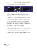
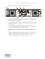
1: Fan outlets: The variable speed fans suck air in through the front vents and out through
the back of the amplifier. Please see maintenance on page 15 for recommendations on how
to clean these and the front foam sections.
2: Link out XLR sockets: These are passively connected directly to their respective inputs to
allow for parallel input connections to other amplifiers. As such, they will function even if the
amplifier is turned off.
3: Input XLR sockets: Connect signal inputs to these sockets, wired pin 2 hot, 3 cold, 1
ground. For sensitivity and impedance of these inputs, please see the specifications on page
16. When running in bridged (mono) mode, only input A is used.
4: Bridged (Mono) switch: Depress this switch to run the amplifier in bridged mode. Note
that the output must be taken from channel A’s output Speakon connector, on pins 2+ hot, 1-
cold.
5: Channel A output Speakon socket: Normal output is on pins 1+ hot, 1- cold. Channel B’s
output is also wired to this socket to enable a single NL4 to provide both channels and to
facilitate easier wiring in bridged mode. Channel B is wired pins 2+ hot, 2- cold.
6: Channel B output Speakon socket: Normal output is on pins 1+ hot, 1- cold.
Input / Link
Pin1 GND
Pin2 +VE
Pin3 -VE
Stereo Mode
Channel A & B Outputs
1+ = +VE
1- = -VE
Class 2 Wiring
on Outputs
To reduce the risk of fire
or electric shock, do not
expose this apparatus to
rain or moisture.
All vents on the front and
rear of the unit must not
be obstructed.
MC
2
Made in England
Serial No.
Lin
k
Inp
ut
Lin
k
Inp
ut
Bridged
Mono
Stereo
Channel B
Channel A
Bridged Mono Mode
Use Channel A Output
2+ = +VE
1- = -VE
Channel B O/P
Channel A O/P
CAUTION
This equipment
must be earthed.
1
2
3
4
6
5

