23
LOWER SYSTEM:
The lower system can be separated from the drive unit (engine, gearbox and handle) without going through the
complete disassembly procedure. If the lower system has not already been separated, follow the appropriate
Gearbox Removal" instructions.
The R270, R450 and R451 rammers use a similarly constructed lower system which is reffered to as the 270 lower
system. The 270 lower system differs from the R374 and R376 lower system, however, due to common design
features, the disassembly procedure is similar.
GUIDE TUBE AND BELLOWS:
1. Drain the oil by removing the Drain Plug (Fig 9,
#23). Tilt the Lower System back until the oil is
drained out.
2. Remove the Guide Tube and Bellows:
Remove twelve bolts and lockwashers (Fig 9,
#31 & #30) between Guide Tube (Fig 9, #3),
Clamp (Fig 9, #5) and Bellows (Fig 9, #6) and
between Bellows, Clamp and Bellow Mount
(Fig 9, #7). Remove Guide Tube and Bellows.
374/6:
Lift the Guide Tube straight off the lower sysĆ
tem. Remove six Whiz Lock Screws between
the Spring Box (Fig 10, #12), Clamp (Fig 10,
#5) and Bellows (Fig 10, #6). Remove Bellows.
3. Remove Slide Bearings (Fig 9, #1) from Guide
Tube. Remove Retaining Ring (Fig 9, #29).
Carefully drive bearings out from the opposite end
of guide tube. Do not scratch or gouge guide tube
walls. Install new slide bearings and retaining ring.
4. Remove the Shoe:
Remove the six Hex Nuts and Lockwashers (Fig
9, #27 & #26) and remove the Shoe (Fig 9,
#25).
374/6:
Remove four Deformed Locknuts, Hex Nuts
and Lockwashers (Fig 10, #29, #28 & #27) reĆ
move Shoe (Fig 10, #25).
5. Lift Bellow Mount (Fig 9, #7) off Spring Box (Fig 9,
#12). Remove and replace bellow mount OĆRing
(Fig 9, #8) (A separate bellow mount is not used on
trench rammers.)
SPRING BOX:
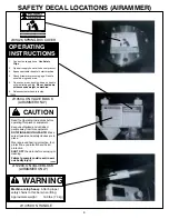
CAUTION: Observe the WARNING LABEL (Fig 9,
#24) on the Spring Box Cover (Fig 9, #20). Follow
the next steps VERY CAREFULLY.
1. Flip Spring Box Assembly (Fig 9, #12) upside
down. Insert two (2) MĆBĆW spring box tools
#06468 from the bottom of the spring box cover
(Tools should be 180
apart).
2. Run the nuts that come with the tools down snug
against the Cover (Fig 9, #20).
3. Remove the Flat Head Socket Screws (Fig 9, #21)
holding the Cover to the Spring Box. The 270
spring box uses three flat head socket screws and
the 374/6 uses two. See figure 5.
FIGURE 5
4. While preventing the bottom of the tool from
turning,
slowly and evenly
back off the nuts on the
cover side. After the tension is removed from the
cover, the tools and the cover can be removed.
5. Remove and replace the OĆRing (Fig 9, #19) from
the Cover (Fig 9, #20).
4. Remove the lower Springs (Fig 9, #13 & #14) from
the spring box.
5. Remove and discard the Elastic Nut (Fig 9, #18).
To remove the nut, place a drift pin or steel rod
through the piston pin hole in the Ram Head (Fig
9, #9) to prevent the ram head from turning while
removing the nut.
6. Remove the Washers (Fig 9, #15), Piston (Fig 9,
#17), Spacer (Fig 9, #16) and upper Springs (Fig
9, #13 & #14).
Summary of Contents for R270R
Page 29: ...27 FIGURE 7 270 450 451 GEARBOX ...
Page 31: ...29 FIGURE 8 374 376 GEARBOX ...
Page 33: ...31 FIGURE 9 270 450 451 LOWER SYSTEM ...
Page 35: ...33 FIGURE 10 374 376 LOWER SYSTEM ...
Page 37: ...35 FIGURE 11 270 450 451 HANDLE ...
Page 39: ...37 FIGURE 12 STANDARD HANDLE OIL INJECTED ONLY ...
Page 41: ...39 FIGURE 13 374 376 HANDLE ...
Page 43: ...41 FIGURE 14 LO PROFILE HANDLE 1 3 6 10 11 13 11 9 ...
Page 45: ...43 FIGURE 15 LO PROFILE HANDLE OIL INJECTED ONLY ...
Page 49: ...47 FIGURE 17 ROBIN ENGINE ...
Page 51: ...49 FIGURE 18 ROBIN OIL INJECTED ENGINE ...
Page 53: ...51 FIGURE 19 LO PROFILE ROBIN ENGINE ...
Page 55: ...53 FIGURE 20 AIRAMMER MOTOR 2 6 5 4 3 1 9 8 7 TO VALVE BLOCK TO MOTOR INLET ...


