SMARTING User Manual
– Release 11/03/2019
11
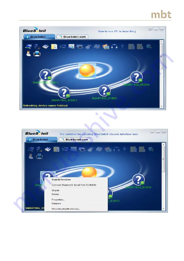
Figure 5.3
Appearance of BlueSoleil Space application after finish of search for
devices.
Figure 5.4
By right mouse clicking on the device, one can recheck the Port number.
In this example the corresponding port number is 24.


