background image

Sprint5000HCS-USA.doc3.doc Page 

01/05/2002 


4

. OPERATION 


4

2

4

2

4

2

4

8

7

14

5

4

3

2

1

9

10

4

11

12

13


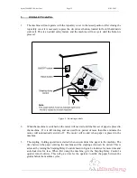
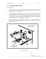
Figure 2 - Control layout 


1  Fold stop lock thumbscrew 

Staple position fine adjustment screw 

2  Stapling head position arm 

On / off button 

3  Edge staple stop thumbscrew 

10

Staple delay knob 

4  Side guide clamping thumbscrew 

11

Staple/fold stop indicator 

5  Staple low indicator / reset 

12

Fold stop tilt adjustment thumbscrew 

6   

13

Staple & fold stops adjustment wheel 

7 Anvil 

14

Counter 


Summary of Contents for SPRINT 5000

Page 1: ...Provided By http www MyBinding com http www MyBindingBlog com MBM Sprint 5000 Booklet Maker Instruction Manual ...

Page 2: ...SPRINT 5000 BOOKLETMAKER OPERATION MANUAL ...

Page 3: ...ng positions 9 4 6 Changing stapling head positions 11 5 Booklet making 12 6 Corner and edge stapling 14 7 Counter 17 8 Replacing stapling heads 17 9 Aligning of stapling heads 17 10 Problem solving 18 Appendix A Parts lists and drawings MBM Corporation Michael Business Machines 3134 Industry Drive North Charleston South Carolina 29418 Customer Service Tel 800 223 2508 Fax 803 552 2974 Parts Servi...

Page 4: ...r The Sprint 5000 is a floor standing machine fitted with sturdy castors and an integral conveyor which can be folded up in order to occupy minimal floor space when not in use This model has five stapling positions to which the stapling heads can be moved according to the size of paper The right hand outside position is for corner stapling A Staple Out Detector is fitted to each of the stapling he...

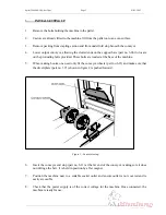
Page 5: ... These bolts are located at the base of the machine 5 When making books one need only fit the conveyor wheels part no 6 13 and make sure that the divert plate part no 3 71 shown in figure 2 is pushed forward Figure 1 Conveyor setup 6 Insert the conveyor end stop part no 6 11 at the far end of the conveyor making sure it does not infringe the belt It is held in position by a flat magnet 7 Position ...

Page 6: ...lock thumbscrew 8 Staple position fine adjustment screw 2 Stapling head position arm 9 On off button 3 Edge staple stop thumbscrew 10 Staple delay knob 4 Side guide clamping thumbscrew 11 Staple fold stop indicator 5 Staple low indicator reset 12 Fold stop tilt adjustment thumbscrew 6 13 Staple fold stops adjustment wheel 7 Anvil 14 Counter ...

Page 7: ... firmly forward Do not allow the cartridge to move backwards once inserted into the stapler If this occurs remove cartridge from stapler and tear off staples at tear line again before re inserting 6 To keep the cartridge in place push metal locking bar down until it snaps into the grove on the back of the cartridge 7 Press staple out reset button lower top cover 8 The staples do not immediately fe...

Page 8: ...Sprint5000HCS USA doc3 doc Page 6 01 05 2002 Figure 3 Staple Out reset indicators ...

Page 9: ...splayed on the legend plate around the switch shown in figure 8 When the stapling head runs out of staples the red light pertaining to that head will illuminate and the booklet maker will not cycle The last set will not be stapled and should be removed from the fold section It can be reprocessed once the staple head s has been refilled 4 3 Staple Jam To clear jammed staples from heads it is best t...

Page 10: ...corresponding to the width of the paper and then re tighten the thumbscrews so that the guides are held in place Figure 4 Side guides 2 Note that the marked settings are meant to be wider than the paper to allow for side jog Both guides move inwards on each cycle to the correct width to ensure that the sheets are aligned before stapling occurs 3 When corner and edge stapling 8 x 11 paper feeding l...

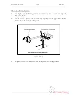
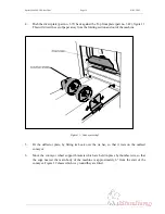
Page 11: ...ions are adjusted as one Loosen fold stop lock thumbscrew figure 5 2 Turn the fold stop adjustment wheel until the staple stop aligns with the appropriate calibration on the scale for the size of paper being used Figure 5 Fold stop 3 Re tighten fold stop lock thumbscrew when the stop has been correctly positioned ...

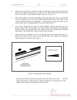
Page 12: ...this can be corrected by adjusting the fold stop tilt thumbscrew figure 6 on the left hand side of the fold stop adjusting shaft Loosen the locking nut and turn the thumbscrew clockwise to raise the left hand end of the fold stop or anti clockwise to lower Tighten locking nut Figure 6 Fold stop tilt ...

Page 13: ... the stapling head hold the slide bracket at the retaining plate end and move to new position 3 Drop the position arm into the new slot on slide bracket which will align the stapling head in the new position Staple head position arms Slide bracket Figure 7 Stapling head adjustment and anvil positions 4 Positions are provided for the various sized books between 4 x 5 and 8 x 11 paper with an additi...

Page 14: ...laced in the machine If it is left running and not used for a period of more than three minutes the motor will automatically switch off The motor will re start when paper is placed in the machine 3 The stapling folding operation is started when sensors detect the paper in the machine The time between the paper entering the machine and the stapling action can be varied This is achieved by turning t...

Page 15: ...Sprint5000HCS USA doc3 doc Page 13 01 05 2002 ...

Page 16: ... The conveyor wheels shown in figure 11 should be adjusted so that the wheels are just over a book s distance from the fold rollers Too close and they will interfere with subsequent booklets coming out of the fold rollers If the wheels are too far away the booklets will have the tendency to insert themselves inside previously ejected booklets 7 Staple Position Fine Adjustment If after correctly se...

Page 17: ...ng move the right hand stapling head to the furthest right position and remove the staple cartridge from the left hand stapling head Then move the left hand stapling head and lock it down in position where it is not over an anvil Alternatively one could also remove the left hand stapling head as described in section 8 concerning replacing stapling heads 3 Turn the corner edge stop adjust thumbscre...

Page 18: ... section and out of the machine Figure 11 Conveyor setup 1 5 Fit the deflector plate by fitting its hook over the tie bar so that it rests on the outfeed conveyor 6 Move the conveyor wheel support brackets which are held in place by thumbscrews so that the edge nearest the main body of the machine is approximately 6 from the start of the conveyor Figure 12 shows which way round they are fitted ...

Page 19: ...set which will lay on top 9 Ensure that the appropriate stapling head s is loaded and the staple cartridge firmly pushed home If staple out system is in use press the staple out reset button Close Perspex cover 10 When hand feeding insert the set to be stapled into the machine underneath the stapling heads until the leading edge touches the paper stops The machine will cycle when the sensors detec...

Page 20: ...ough in which the bar at the back of the stapling head is located 4 Take the bar from the trough and having removed the head completely replace the retaining plate in it s original position and tighten the bolt 5 To re fit a new head place the bar at the back of the stapling head into the trough position the retaining plate over the top and tighten the bolt and replace the spring clip Replace elec...

Page 21: ...c3 doc Page 19 01 05 2002 4 Locate pip on adjustment guide into small hole at front of anvil and then retighten hex screws The stapling head should now be in a position to carry on stapling after removing adjustment guide ...

Page 22: ...n to allow photo cell to reset Stapling head jammed Incorrectly fitted staple cartridge Switch off machine lift safety cover remove cartridge clear jammed staples and replace Repeated jamming of stapling head Miss aligned head with anvil Check alignment of stapling head and anvil Staple legs breaking Miss aligned head with anvil Check alignment of stapling head and anvil One staple not on fold lin...

Reviews:

Related manuals for SPRINT 5000