background image

Basic Climate Control 

Fundamentals 

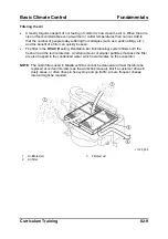
Filtering the Air 

• 

A mostly forgotten aspect of our feeling of comfort is how clean the air is. When the air is 
clean it feels comfortable even at warmer or colder temperatures than normal. Add to 
that the number of people today suffering from allergies (such as a pollen allergy etc.), 
and the benefit of a filter can quickly be seen.  

• 

The filter in the 

HVAC

 (

H

eating, 

V

entilation, 

A

ir 

C

onditioning) system filters both the 

fresh air and the recirculated air. A certain amount of smaller particles that pass the filter 
are also trapped in the condensed water, which accumulates on the evaporator.  


NOTE

:  The cabin filters used in Mazda vehicles cannot be cleaned and must therefore be 

replaced at certain intervals (see the workshop manual). But if a customer drives in 
dusty areas, or often drives in heavy stop and go traffic, a more frequent change 
interval might be required. 


L1005_009 


Unfiltered air 

Filtered air 

2 Air 

filter 


Curriculum Training 

02-9 

Summary of Contents for CT-L1005

Page 1: ...Training Manual Basic Climate Control CT L1005...

Page 2: ...ation data and descriptive text in this issue to the best of our knowledge were correct at the time of going to print No liability can be accepted for any inaccuracies or omissions in this publication...

Page 3: ...ironmental Impact 02 12 Compressor Oil 02 13 Moisture in the A C System 02 13 A C System 03 1 System Overview 03 1 A C System with Expansion Valve 03 3 Parts Location 03 3 Compressor 03 4 Vane Rotary...

Page 4: ...Heating System 04 1 System Overview 04 1 Thermostat 04 2 Heater Core 04 2 Water Pump 04 2 Radiator 04 2 Diagnosis and Repair 05 1 Pressure Gauges 05 1 Refrigerant Pressure Check 05 2 Leak Testing 05 4...

Page 5: ...agnosing and repairing climate control system related concerns requires working with a refrigerant under pressure Improper handling of the refrigerant could lead to serious injuries Follow the safety...

Page 6: ...iagnosis and Repair NOTE The data tables and procedures presented in this training manual serve only as examples They are taken from the service literature and subjected to major or minor changes over...

Page 7: ...eople find it comfortable based on the air temperature and relative humidity There are also other factors not shown on this graph that affect our comfort such as how clean the air is and if there is a...

Page 8: ...g clothes off and putting clothes on So a vehicle has a climate control system to allow the driver to create a comfortable climate To allow the driver to do this it has to be possible to change the tw...

Page 9: ...ambient temperature of the room The heat travels from the warmer surroundings to the cooler water L1005_001 In the second example a hot cup of coffee is brought into a warm room The coffee gives off t...

Page 10: ...room The heater core gives its heat up to the outside air that comes in contact with the fins The heat travels from the warm heater core to the cold air Unlike the coffee in our example the heater cor...

Page 11: ...uid As the warm air comes in contact with the fins of the evaporator the heat from the warm air is conducted through the metal fins and warms the refrigerant flowing through the internal passageways T...

Page 12: ...ll of the ice is melted does the temperature start to rise again in direct relation to the amount of heat added stage 3 This is because the energy added is no longer required to change the ice to wate...

Page 13: ...als L1005_022 X Heat energy Y Temperature 1 Ice being warmed 5 Steam being warmed 2 Ice changing to water 6 Latent heat of fusion 3 Water being warmed 7 Latent heat of vaporization 4 Water changing to...

Page 14: ...air this is determined by the dew point which depends on the current air temperature and the relative humidity of the air Operating the A C allows the evaporator to cool down and for the moisture in t...

Page 15: ...Heating Ventilation Air Conditioning system filters both the fresh air and the recirculated air A certain amount of smaller particles that pass the filter are also trapped in the condensed water which...

Page 16: ...NOTE Older Mazda vehicles use R12 refrigerant which must not be used anymore In addition R12 and R134a must not be mixed Pressure Temperature Relationship of R134a This chart shows the relationship be...

Page 17: ...the pressure will then increase rapidly and the container could rupture CAUTION Filling a container more than 60 and storing a container near sources of heat or in direct sunlight can cause serious i...

Page 18: ...king in a pit or other low lying area while servicing the A C is not recommended because large amounts of released refrigerant could displace the air and cause suffocation While R134a is not flammable...

Page 19: ...servicing a vehicle the correct oil needs to be put into the A C system NOTE Compressor oil needs to be properly disposed of just like any other environmentally harmful fluids brake fluid engine coola...

Page 20: ...Fundamentals Basic Climate Control Notes 02 14 Curriculum Training...

Page 21: ...em from the low pressure side and throttles the refrigerant bringing it to its coldest temperature The other system used is the fixed orifice system which has the same function as the expansion valve...

Page 22: ...air coming in contact with the fins of the condenser absorbs the heat from the refrigerant cooling it and liquifying it The liquid then travels to the expansion valve or the fixed orifice where it is...

Page 23: ...essure gas This gas then moves into the compressor where the pressure and temperature are increased The cycle then continues A C System with Expansion Valve Parts Location L1005_029 1 Compressor 6 Rig...

Page 24: ...ad from the engine see the section Control The compressor is one of the two components that separate the high pressure side of the A C system from the low pressure side Compression Plotted on the Refr...

Page 25: ...entrically mounted rotor with vanes that are thrown out by centrifugal force to create a seal against the housing As the rotor moves through its eccentric path the chamber becomes smaller compressing...

Page 26: ...helix mounted so that the moving helix creates a chamber that draws the refrigerant in seals the chamber off and compresses the refrigerant L1005_036 1 Thrust plate 5 Moving helix 2 Fixed helix 6 Ball...

Page 27: ...mounted at an angle on a shaft The swash plate moves a number of double acting pistons to draw in and compress the refrigerant Reed valves control the induction and compression of the refrigerant L10...

Page 28: ...below Point 2 represents the stage in the A C system after the refrigerant has left the compressor and before it enters the condenser At this point the refrigerant is a high pressure high temperature...

Page 29: ...Tube Condenser The refrigerant flows through tubes laid out in a serpentine path The fins brazed to the tubes increase the transfer of heat from the refrigerant to the ambient air L1005_042 1 Fins 2 R...

Page 30: ...aller channels resulting in more heat transfer than in a fin and tube condenser In addition the refrigerant is sent through the condenser in a parallel flow increasing the cooling performance even mor...

Page 31: ...denser Incorporating the receiver drier into the condenser ensures that at this last sub cooling stage no 4 in the illustration only liquid refrigerant is being cooled NOTE Depending on the model the...

Page 32: ...oir the liquid refrigerant in the receiver drier helps to compensate when there are changes in the cooling demands and the amount of liquid refrigerant needed in the evaporator fluctuates To make sure...

Page 33: ...n 3 hours the desiccant will be saturated and the surplus moisture will cause the PAG oil to break down Any water not able to be trapped by the desiccant can also mix with the refrigerant creating a c...

Page 34: ...rant through the expansion valve In this way the heat absorbing performance of the evaporator is adapted to the actual demand Expansion Plotted on the Refrigerant Curve L1005_023c X Pressure Y Tempera...

Page 35: ...more refrigerant in the evaporator to absorb heat and the refrigerant temperature will decrease Then the process continues Expansion Valve L1005_011 1 Diaphragm 8 Spring force 2 Reference chamber fill...

Page 36: ...ling through the inside of the evaporator The heat is absorbed by the refrigerant as it changes its state from a liquid to a gas Vaporisation Plotted on the Refrigerant Curve L1005_023d X Pressure Y T...

Page 37: ...The refrigerant flows through tubes that have fins attached to them to allow for heat dissipation Internal flow of refrigerant through the evaporator L1005_010 1 Liquid refrigerant from expansion valv...

Page 38: ...It is normal that during operation of the A C a pool of water may appear underneath the vehicle If the condensed water on the surface of the evaporator does begin to freeze then it could lead to reduc...

Page 39: ...lines in the A C circuit are rigid Depending on the type of connection there may be a special procedure or a special tool required L1005_026 1 Male side block 3 Pliers to hold the female side 2 Femal...

Page 40: ...system is either too low or too high it can cause damage to the rest of the system For example when the pressure is too low there will be less refrigerant delivered to the compressor Because the comp...

Page 41: ...pressor pulley to the compressor drive shaft When electrical current flows through the field coil a magnetic force is created which pulls the drive plate against the rotating compressor pulley Consequ...

Page 42: ...example under certain operating conditions such as high engine load high coolant temperature or high engine speed the PCM will not turn the compressor on The magnetic clutch is equipped with a therma...

Page 43: ...er from those found in the A C system with expansion valve Parts Location L1005_030 1 Compressor 6 High pressure service valve 2 Condenser 7 Rigid refrigerant lines 3 Fixed orifice 8 A C cycling switc...

Page 44: ...sor functions similar to the standard swash plate compressor described earlier The two major differences are the variable swash plate and the control valve The control valve controls the pressure on t...

Page 45: ...ce can be located a bit further away from the evaporator On the Tribute the flow rate of the refrigerant through the fixed orifice is determined by the cycling of the compressor On the Mazda2 and Mazd...

Page 46: ...A C System Basic Climate Control The tools shown below are required to service the fixed orifice L1005_047 1 Removal and installation tool 2 Damaged orifice removal tool 03 26 Curriculum Training...

Page 47: ...er certain operating conditions allow liquid refrigerant to exit the evaporator Because of this the accumulator drier also functions as a second evaporator to ensure that no liquid refrigerant is pass...

Page 48: ...quired to determine the amount of compressor oil to be added to the new accumulator drier such as draining the compressor oil from the old accumulator drier Control A C Cycling Switch The A C cycling...

Page 49: ...medium and a high pressure switch The medium pressure switch outputs a cooling fan control signal to the PCM depending on the condenser load The high pressure switch is connected in series to the A C...

Page 50: ...A C System Basic Climate Control Wiring Diagram L1005_048 1 PCM 4 A C cycling switch 2 A C relay 5 High pressure switch 3 Magnetic clutch 6 Medium pressure switch 03 30 Curriculum Training...

Page 51: ...type Mazda3 Diesel x Variable displacement Swash Plate Multiflow Mazda5 x Vane rotary Multiflow sub cooling type Mazda6 x Vane rotary Multiflow sub cooling type x MPV LW x Scroll Multiflow sub cooling...

Page 52: ...A C System Basic Climate Control Notes 03 32 Curriculum Training...

Page 53: ...assenger compartment which gives the heat up to the incoming air The coolant circulates in two circuits the small and the big circuit In the small circuit the water pump circulates the coolant past th...

Page 54: ...lly the opposite function of the evaporator The hot coolant flowing through the tubes of the heater core releases its heat to the air passing through the fins of the heater core The fins which are bra...

Page 55: ...C is activated the pressure on the high pressure side will increase and the pressure on the low pressure side will settle to its operating condition Until this occurs there can be no cooling effect e...

Page 56: ...perating see the workshop manual for the vehicle specific procedure The measurements are then compared to values in a graph such as the sample graph shown below L1005_055 Excerpt from Mazda3 Workshop...

Page 57: ...5 bar High pressure side 2 3 MPa 23 bar Air in system Low pressure side 0 05 MPa 0 5 bar to 1 5 MPa 15 bar High pressure side 0 7 MPa 7 bar to 1 5 MPa 15 bar Moisture in system Low pressure side 0 075...

Page 58: ...and where leak checking plays a very unimportant role The normal seepage of an automotive A C system cannot be stopped and these minuscule leaks should not be taken into consideration during leak tes...

Page 59: ...ic value COLP should read ON In addition the user can actively send an output signal to the A C relay to check the integrity of the control circuit To do this the PID ACCS must be activated using the...

Page 60: ...pump to draw the refrigerant out During this process the machine will either manually or automatically weigh the amount of refrigerant taken from the system This is the only 100 reliable way of verify...

Page 61: ...erant from the system Was approximately the correct amount of refrigerant drained No Follow the Workshop manual procedures to find and repair the leak Yes Evacuate the system using a deep vacuum Does...

Page 62: ...p manual will give an amount of oil that should be added This ensures proper lubrication of the compressor NOTE When lubricating the O rings with compressor oil use a lint free cloth to apply the oil...

Page 63: ...fected components must be replaced Failure to do so may result in the new compressor being damaged again NOTE On an A C system with a fixed orifice the accumulator drier can be especially succeptible...

Page 64: ...much ethylene glycol reduces the heat capacity of the coolant and hence the heating performance of the heater core See the service literature for the correct mixture Thermostat If the thermostat is s...

Page 65: ...iations A C Air Conditioning HVAC Heating Ventilation Air Conditioning OSC Output State Control PAG Poly Alkaline Glycol PCM Powertrain Control Module PID Parameter Identification WDS Worldwide Diagno...

Page 66: ...List of Abbreviations Basic Climate Control Notes 06 2 Curriculum Training...

Reviews: