


Black plate (304,1)
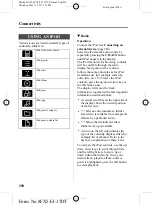
Frequency
Band MHz
Maximum output power Watt (Peak RMS)
Aerial Positions
1 - 30
100 W
8
50 - 54
100 W
3, 4, 5
68 - 87.5
50 W
3, 4, 5
142 - 176
50 W
3, 4, 5
220 - 225
50 W
3, 4, 5
380 - 512
50 W
3, 4, 5
806 - 870
10 W
3, 4, 5, 6
*
, 7
*
870 - 940
10 W
3, 4, 5, 6
*
, 7
*
1200 - 1400
10 W
3, 4, 5
1710 - 1885
10 W
3, 4, 5, 6
*
, 7
*
1885 - 2025
10 W
3, 4, 5, 6
*
, 7
*
*
Only for GSM/3G cellular phones, with a patch aerial installed inside of the front windscreen.
NOTE
l
Position 6 & 7 are patch aerials, 8 is the towbar.
l
After the installation of RF transmitters, check for disturbances from and to all
electrical equipment in the vehicle, both in the standby and transmit modes.
Check all electrical equipment:
l
with the ignition
ON
l
with the engine running
l
during a road test at various speeds.
Check that electromagnetic fields generated inside the vehicle cabin by the transmitter
installed do not exceed applicable human exposure requirements.
296
Appendices
Mazda BT-50_8FX5-EI-17DT_Edition2 Page304
Thursday, May 11 2017 5:35 PM
Form No.8FX5-EI-17DT