background image

GENERAL INFORMATION 

00–00–11

00–00

Engine Workshop Manual 13B-MSP (Multi Side Port) (1773–1U–03C)

SAE STANDARDS

CHU000000003E02

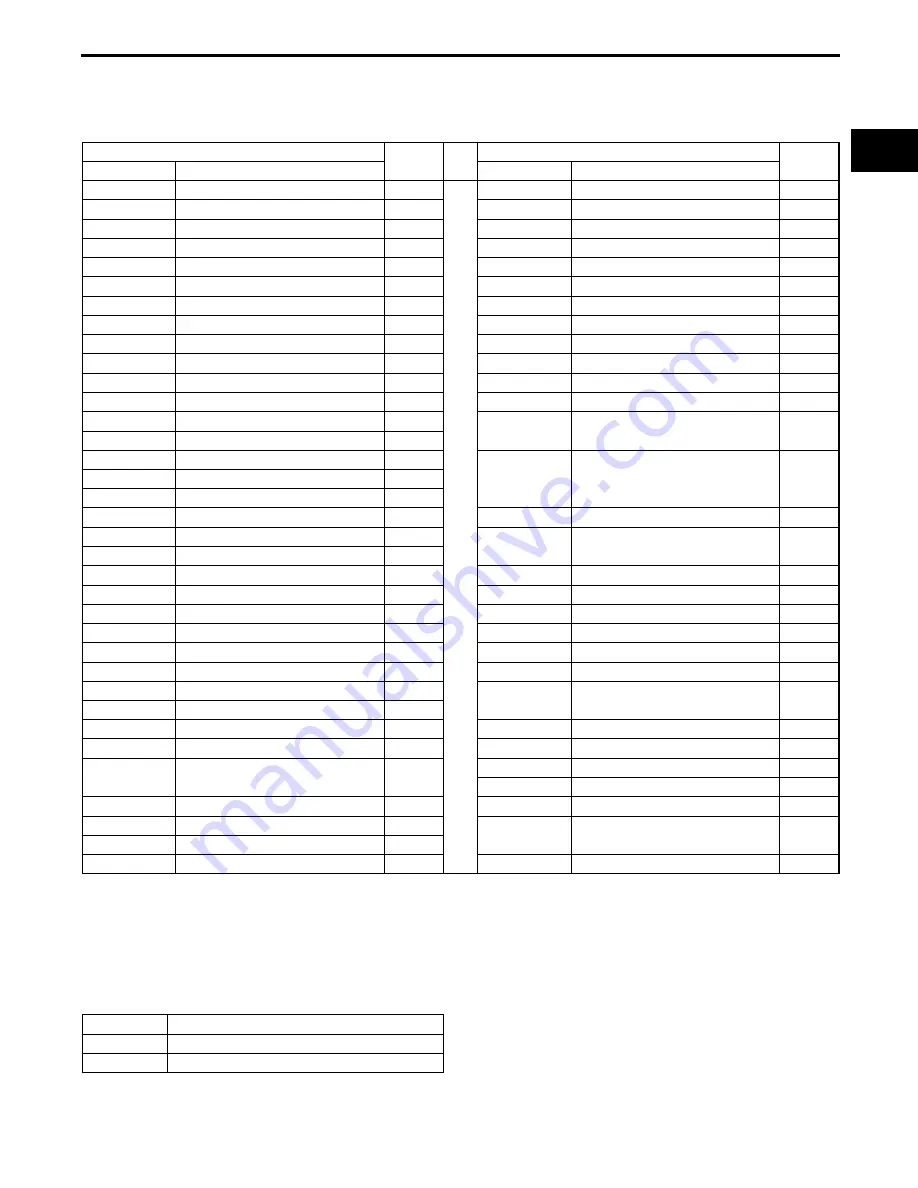
In accordance with new regulations, SAE (Society of Automotive Engineers) standard names and abbreviations 
are now used in this manual. The table below lists the names and abbreviations that have been used in Mazda 
manuals up to now and their SAE equivalents.

#1 : Diagnostic trouble codes depend on the diagnostic test mode.
#2 : Controlled by the PCM
#3 : Device that controls engine and powertrain
#4 : Directly connected to exhaust manifold

End Of Sie

ABBREVIATIONS

CHU000000011E01

End Of Sie

SAE Standard

Remark

SAE Standard

Remark

Abbreviation

Name

Abbreviation

Name

AP

Accelerator Pedal

MAP

Manifold Absolute Pressure

APP

Accelerator Pedal Position

MAF

Mass Air Flow

ACL

Air Cleaner

MAF sensor

Mass Air Flow Sensor

A/C

Air Conditioning

MFL

Multiport Fuel Injection

A/F

Air Fuel Ratio

OBD

On-board Diagnostic System

BARO

Barometric Pressure

OL

Open Loop

B+

Battery Positive Voltage

OC

Oxidation Catalytic Converter

CMP sensor

Camshaft Position Sensor

O2S

Oxygen Sensor

LOAD

Calculated Load Value

PNP

Park/Neutral Position

CAC

Charge Air Cooler

PID

Parameter Identification

CLS

Closed Loop System

PSP

Power Steering Pressure

CTP

Closed Throttle Position

PCM

Powertrain Control Module

#3

CPP

Clutch Pedal Position

PAIR

Pulsed Secondary Air Injection

Pulsed 
injection

CIS

Continuous Fuel Injection System

CKP sensor

Crankshaft Position Sensor

AIR

Secondary Air Injection

Injection 
with air 
pump

DLC

Data Link Connector

DTM

Diagnostic Test Mode

#1

DTC

Diagnostic Test Code(s)

SAPV

Secondary Air Pulse Valve

DI

Distributor Ignition

SFI

Sequential Multiport Fuel 
Injection

DLI

Distributorless Ignition

EI

Electronic Ignition

#2

3GR

Third Gear

ECT

Engine Coolant Temperature

TWC

Three Way Catalytic Converter

EM

Engine Modification

TB

Throttle Body

EVAP

Evaporative Emission

TP

Throttle Position

EGR

Exhaust Gas Recirculation

TP sensor

Throttle Position Sensor

FC

Fan Control

TCC

Torque Converter Clutch

FF

Flexible Fuel

TCM

Transmission (Transaxle) Control 
Module

4GR

Fourth Gear

GEN

Generator

TR

Transmission (Transaxle) Range

GND

Ground

TC

Turbocharger

HO2S

Heated Oxygen Sensor

With 
heater

VSS

Vehicle Speed Sensor

VR

Voltage Regulator

IAC

Idle Air Control

VAF sensor

Volume Air Flow Sensor

IAT

Intake Air Temperature

WU-TWC

Warm Up Three Way Catalytic 
Converter

#4

KS

Knock Sensor

MIL

Malfunction Indicator Lamp

WOP

Wide Open Throttle

AT

Automatic Transmission

MT

Manual Transmission

SST

Special Service Tool

Summary of Contents for 13B-MSP

Page 1: ...2008 Mazda Motor Corporation PRINTED IN U S A OCTOBER 2008 up to October 2008 Any changes that occur Part No 9999 95 E13B MSP09...

Page 2: ...val Disassembly 00 00 6 Arrangement of Parts 00 00 7 Cleaning of Parts 00 00 7 Reassembly 00 00 7 Adjustment 00 00 8 Rubber Parts and Tubing 00 00 8 Hose Clamps 00 00 8 Torque Formulas 00 00 8 Vise 00...

Page 3: ...ents of the procedures are explained in detail and shown in the illustrations 49 H002 671 49 H032 322 49 1232 670A SHOWS PROCEDURE ORDER FOR SERVICE Fluid Pressure Inspection 1 Assemble the SSTs as sh...

Page 4: ...Expendable parts tightening torques and symbols for oil grease and sealant are shown in the overview illustration In addition symbols indicating parts requiring the use of special service tools or equ...

Page 5: ...added information that will help you to complete a particular procedure Specification The values indicate the allowable range when performing inspections or adjustments Upper and lower limits The val...

Page 6: ...0 kPa 2 1 2 7 kgf cm2 30 38 psi 270 310 kPa 2 7 3 2 kgf cm2 39 45 psi The actual converted values for 2 7 kgf cm2 are 264 kPa and 38 4 psi In the first specification 2 7 is used as an upper limit so t...

Page 7: ...e required Disassembly If the disassembly procedure is complex requiring many parts to be disassembled all parts should be marked in a place that will not affect their performance or external appearan...

Page 8: ...using compressed air Reassembly Standard values such as torques and certain adjustments must be strictly observed in the reassembly of all parts If removed the following parts should be replaced with...

Page 9: ...e Formulas When using a torque wrench SST or equivalent combination the written torque must be recalculated due to the extra length that the SST or equivalent adds to the torque wrench Recalculate the...

Page 10: ...0000006E01 Connectors Disconnecting connectors When disconnecting connector grasp the connectors not the wires Connectors can be disconnected by pressing or pulling the lock lever as shown Locking con...

Page 11: ...from the wiring harness side Inspect the terminals of waterproof connectors from the connector side since they cannot be accessed from the wiring harness side Caution To prevent damage to the terminal...

Page 12: ...PID Parameter Identification CLS Closed Loop System PSP Power Steering Pressure CTP Closed Throttle Position PCM Powertrain Control Module 3 CPP Clutch Pedal Position PAIR Pulsed Secondary Air Inject...

Page 13: ...CHU000000000E01 Because the engine construction varies depending on the vehicle s period of manufacture determine the service specification by referring to the following identification Identifying Sp...

Page 14: ...Spring 01 10 19 Corner Seal Spring 01 10 19 Apex Seal Spring 01 10 19 ROTOR BEARING OIL CLEARANCE INSPECTION 01 10 20 ROTOR BEARING REPLACEMENT 01 10 21 Removal 01 10 21 Installation 01 10 21 ECCENTRI...

Page 15: ...ted to an impact against a level surface Always set two pieces of wood in the positions shown in the figure to prevent the oil pan from being dented If the oil pan is dented the amount of intake oil a...

Page 16: ...shown in the figure 2 Mount the engine to the SST engine stand 3 Remove the oil pan drain plug and drain the engine oil 4 Install the oil pan drain plug with a new washer Tightening torque Type A 29 4...

Page 17: ...the order indicated in the table Type A 9 8 7 5 4 1 2 10 11 6 R R R 3 R R BHJ0110E006 1 Oil filter component 2 Engine hanger engine rear side 3 Engine coolant temperature sensor 4 Engine hanger engin...

Page 18: ...1 2 R 3 4 6 7 11 9 10 8 12 R BHJ0110F002 1 Engine hanger engine rear side 2 Engine coolant temperature sensor 3 Engine hanger engine front side 4 Water pump body 5 Thermostat component 6 Oil pan See 0...

Page 19: ...MECHANICAL 01 10 4 2 Engine Workshop Manual 13B MSP Multi Side Port 1773 1U 03C THIS PAGE INTENTIONALLY LEFT BLANK...

Page 20: ...ulti Side Port 1773 1U 03C Revised 6 2008 Ref No R108 08 Oil Pan Disassembly Note 1 Remove the oil pan using the separator tool Oil Pan Upper Block Disassembly Note 1 Remove the oil pan upper block us...

Page 21: ...isassembly Note 2 Pulley component 3 Eccentric shaft bypass valve 4 Spring 5 Front cover See 01 10 7 Front Cover Disassembly Note 6 Front oil seal 7 Plug 8 Control valve spring 9 Control valve 10 Mete...

Page 22: ...lockbolt See 01 10 7 Pulley Lockbolt Disassembly Note 2 Pulley component 3 Eccentric shaft bypass valve 4 Spring 5 Front cover See 01 10 7 Front Cover Disassembly Note 6 Front oil seal 7 OCV 8 Oil pip...

Page 23: ...MECHANICAL 01 10 6 2 Engine Workshop Manual 13B MSP Multi Side Port 1773 1U 03C THIS PAGE INTENTIONALLY LEFT BLANK...

Page 24: ...the figure Oil Pump Sprocket Disassembly Note 1 Lock the flywheel MT or counterweight AT against rotation using the SST 2 Unlock the crimped part of the lock washer and remove the locknut and lock wa...

Page 25: ...n the table R SST R R R R R R R R 9 8 7 5 4 3 10 19 18 17 15 16 14 13 11 12 6 1 R R 2 SST AT 1 A B C D E G F H I 20 21 22 SST SST SST SST BHJ0110E010 1 Flywheel MT counterweight AT See 01 10 9 Flywhee...

Page 26: ...11 Rotor Housing Disassembly Note 9 Rear rotor A Side seal B Side seal spring C Corner seal D Corner seal plug E Corner Seal Spring F Side piece G Apex seal H Apex seal spring short I Apex seal spring...

Page 27: ...housing to the left and right to cut the oil film 2 Remove the rear housing Caution If a seal adheres to the rear housing put it back in its original position in the rotor Stationary Gear Disassembly...

Page 28: ...ing on the engine rear side and place them in the SST while keeping them in order 2 Move the rotor to the left and right to cut the oil film 3 Remove the rotor Caution If a seal adheres to the side ho...

Page 29: ...Rotate and remove the intermediate housing at the point where the eccentric shaft does not catch Caution If a seal adheres to the intermediate housing put it back in its original position in the roto...

Page 30: ...place the corresponding side housing 2 Inspect the side housing for distortion in four positions as shown in the figure using a straight edge and a feeler gauge If the distortion exceeds the maximum r...

Page 31: ...E01 1 Measure the width of the rotor housing at four points A B C and D as shown in the figure using a micrometer 2 Compute the width variation If it exceeds the maximum replace the rotor housing Widt...

Page 32: ...measurements from 1 and 2 Rotor and side housing clearance rotor housing width maximum rotor width Standard clearance 0 05 0 19 mm 0 0020 0 0074 in Minimum clearance 0 05 mm 0 002 in 2 Measure the pr...

Page 33: ...e clearance between the apex seal groove and the apex seal using a feeler gauge If it exceeds the maximum specification replace the apex seal If the clearance is still not within the standard after re...

Page 34: ...nto the tapered surface side of the side seal as shown in the figure and fix the side seal by pressing uniformly so that it contacts the inner side of the groove straight surface Caution Press the fee...

Page 35: ...using a vernier caliper If either of the items exceeds the maximum specification replace the oil seal 1 Width of area that contacts the oil seal lip Caution Measure the contact width around the comple...

Page 36: ...tion 0 5 mm 0 02 in Side Seal Spring 1 Assemble the side seal spring into the rotor 2 Assemble the side seal into the rotor 3 Measure the side seal projection using a vernier caliper If it is less tha...

Page 37: ...not contact the rotor bearing 2 Measure the inner diameter of the rotor bearing using a cylinder gauge 3 Calculate the rotor bearing oil clearance from the rotor journal outer diameter and the rotor...

Page 38: ...the rotor bearing using the SST Installation 1 Remove the SST handle 2 Temporarily assemble so that the rotor bearing tab and the rotor notch are aligned after pressing in the rotor bearing and rotor...

Page 39: ...dial gauge If it exceeds the maximum specification replace the eccentric shaft Standard runout 0 02 mm 0 0008 in Maximum runout 0 06 mm 0 0024 in End Of Sie ECCENTRIC SHAFT END PLAY INSPECTION CHU011...

Page 40: ...entric shaft using a dial gauge If not within the specification replace the spacer with one that is thicker than the currently assembled one If it exceeds the specification replace with a thinner spac...

Page 41: ...If there is any malfunction replace the pilot bearing Replacement Removal 1 Fix the eccentric shaft on a vice 2 Remove the pilot bearing and the oil seal together using the SST Installation 1 Install...

Page 42: ...ification replace the eccentric shaft bypass valve Minimum projection 6 mm 0 24 in End Of Sie ECCENTRIC SHAFT POSITION PLATE INSPECTION CHU011011D01E05 1 Visually inspect the eccentric shaft position...

Page 43: ...ntric shaft Standard main bearing oil clearance Without stopper screw 0 045 0 085 mm 0 0018 0 0033 in With stopper screw 0 055 0 075 mm 0 0022 0 0029 in Maximum main bearing oil clearance Without stop...

Page 44: ...n the gear of the stationary gear downward and install the main bearing by pressing it with the SST Caution Press the main bearing in so that the top of the main bearing is flush with the top of the s...

Page 45: ...all the main bearing using the SST Caution Press the main bearing in so that the top of the main bearing is flush with the top of the stationary gear flange 4 Apply thread locking compound to the stop...

Page 46: ...p clearance 0 15 mm 0 0059 in 3 Measure the side clearance between the rotor and the side housing using a straight edge and a feeler gauge If it exceeds the maximum specification replace the oil pump...

Page 47: ...er O ring small radius See 01 10 31 O Ring Assembly Note 3 Inner oil seal See 01 10 32 Oil Seal Assembly Note 4 Outer oil seal spring See 01 10 30 Oil Seal Spring Assembly Note 5 Outer O ring large ra...

Page 48: ...tion lock slots on the oil seal can be used as a reference Assemble the rounded end within 0 15 mm 0 0 59 in away from the oil seal spring rotation lock O Ring Assembly Note 1 Apply petroleum jelly to...

Page 49: ...oil seal is smooth and there is no catching by pushing the oil seal with your hand Cut Off Seal Spring Assembly Note 1 Assemble the cut off seal spring with the spring end turned upward Note When rep...

Page 50: ...33 01 10 Cut Off Seal Assembly Note 1 Assemble the cut off seal so that it does not run over the rotation lock pin End Of Sie ROTOR ROTATION LOCK PIN CUT OFF SEAL CUT OFF SEAL SPRING GOOD NO GOOD NO...

Page 51: ...OIL OIL OIL OIL OIL OIL 9 8 7 5 4 3 10 19 18 17 15 16 14 13 11 12 6 1 2 R R OIL OIL AT SST A B C D E G F H I P P P P N m kgf m ft lbf 68 6 78 4 6 70 7 99 50 6 57 8 31 4 39 2 3 21 3 99 23 2 28 9 392 49...

Page 52: ...l ball 8 Spring 9 Oil jet plug See 01 10 36 Oil Jet Plug Assembly Note 10 Eccentric shaft 11 Front rotor housing See 01 10 37 Rotor Housing Assembly Note 12 Tubular dowel front rotor housing side 13 I...

Page 53: ...troleum jelly between the corner seal and corner seal groove 7 Place the rotor in the housing 8 Insert the SST into the apex seal groove of the rotor and verify that the apex seal groove of the corner...

Page 54: ...tion shown in the figure 3 Assemble the inner seal rubber to the housing with the seal rubber joint placed between A B 4 Apply the silicone sealant to the position indicated in the figure Bead thickne...

Page 55: ...gine rear side 7 Assemble the apex seal spring long while pressing the apex seal spring short Caution Assemble the apex seal spring until it catches the spring stopper of the side piece Intermediate H...

Page 56: ...aught between the rotor housing and intermediate housing Rear Oil Seal Assembly Note 1 Assemble the oil seal using the SST Caution Insert the rear oil seal until it is reaches to the seating face GOOD...

Page 57: ...engine oil to the tension bolt threads and assemble to the housing with a new seal washer Caution Assemble a tension bolt which has a seal washer with the rubber projection facing the housing side 2...

Page 58: ...l MT Counterweight AT Assembly Note 1 Lock the flywheel MT or counterweight AT against rotation using the SSTs 2 Tighten the locknut using the SST Tightening torque 392 490 N m 40 0 49 9 kgf m 290 361...

Page 59: ...0E001 1 Oil pump body 2 Shaft 3 Front inner rotor 4 Front outer rotor 5 Middle plate 6 Rear inner rotor 7 Rear outer rotor 8 Spacer See 01 10 43 Spacer Assembly Note 9 Needle bearing 10 Thrust plate 1...

Page 60: ...10 kgf cm 69 0 95 5 in lbf 7 8 10 8 80 110 kgf cm 69 0 95 5 in lbf 7 8 10 8 80 110 kgf cm 69 0 95 5 in lbf 254 294 25 9 29 9 188 216 GHE0110E003 1 Spacer See 01 10 43 Spacer Assembly Note 2 Needle bea...

Page 61: ...MECHANICAL 01 10 42 2 Engine Workshop Manual 13B MSP Multi Side Port 1773 1U 03C THIS PAGE INTENTIONALLY LEFT BLANK...

Page 62: ...p chain engaged Oil Pump Sprocket Wheel Assembly Note 1 Lock the flywheel MT and counterweight AT against rotation using the SSTs 2 Assemble the oil pump shaft with a new lock washer and locknut and t...

Page 63: ...r shown in the figure Tightening torque 18 6 25 5 N m 1 90 2 60 kgf m 13 8 18 8 ft lbf Pulley Lockbolt Assembly Note 1 Lock the flywheel MT or counterweight AT against rotation using the SSTs 2 Apply...

Page 64: ...5 1 9 2 6 13 8 18 8 7 8 10 8 80 110 kgf cm 69 0 95 5 in lbf 8 8 11 8 90 120 kgf cm 78 104 in lbf N m kgf m ft lbf R R R R 14 2 17 2 1 45 1 75 10 5 12 6 SEALANT R 15 7 23 5 1 61 2 39 11 6 16 5 7 8 10 8...

Page 65: ...80 110 kgf cm 69 0 95 5 in lbf 18 6 25 5 1 90 2 60 13 8 18 8 18 6 25 5 1 90 2 60 13 8 18 8 18 6 25 5 1 90 2 60 13 8 18 8 18 6 25 5 1 90 2 60 13 8 18 8 31 4 46 1 3 21 4 70 23 2 34 0 15 7 23 5 1 61 2 39...

Page 66: ...6 in 4 Install the oil pan upper block to the housing 5 Tighten the oil pan upper block installation bolts Tightening torque 18 6 25 5 N m 1 9 2 6 kgf m 13 8 18 8 ft lbf Oil Pan Assembly Note Type A C...

Page 67: ...ing 1 Completely clean and remove any oil dirt sealant or other foreign material that may be adhering to the oil pan upper block and oil pan 2 When reusing the oil pan installation bolts clean any old...

Page 68: ...EX SEAL SPRING Apex seal height mm in Standard 5 3 0 20 Minimum 4 3 0 17 Apex seal spring height mm in Standard 5 4 0 213 Minimum 3 5 0 148 CORNER SEAL CORNER SEAL SPRING Minimum projection of the cor...

Page 69: ...nd Of Sie OIL PUMP Body clearance Type A mm in Standard 0 20 0 25 0 0079 0 0098 Maximum 0 3 0 0118 Tip clearance Type A mm in Standard 0 03 0 12 0 0012 0 0047 Maximum 0 15 0 0059 Side clearance Type A...

Page 70: ...5 Flywheel box wrench 49 0839 305A Counterweight puller 49 F011 101 Ring gear brake MT 49 0813 250 Seal case 49 0813 215A Dowel puller and oil pump puller 49 0813 225A Oil seal remover 49 0813 235 Mai...

Page 71: ......

Reviews: