background image


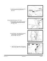
Red LED 

HomeLink Buttons 


4.  Turn the ignition key to the OFF position. 


5.  Push each HomeLink®  button, one at a time, and  


     verify that LED indicator to the left of the center  


     switch illuminates with a red LED.  (Fig.  8-2) 


6.  Testing is now complete. 


1.  Trim excess off all wire ties. 


2.  Reinstall in reverse order, all trim pieces removed  


     during installation. 


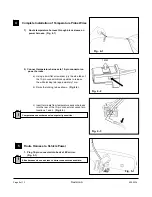
3.  Place User Guide in vehicle glove-box.   (Fig.  9-1)   


4.  Remove fingerprints, smudges, dirt, etc. from mirror. 


5.  Verify each reinstalled component for proper fit and  


     function. 


1.  Adjust compass zone after EC mirror installation. 


a)  The zone setting is factory preset to Zone 8.  


     Refer to Compass Calibration Zone Map  


 (Fig.  10-1)

 to find correct compass zone setting 


     for your geographical location.  Use same map 


     from User Guide. 


b)  To change the zone setting, push and hold the 


     right button until a number appears in the display.  


     Press button repeatedly until desired compass 


     zone number is reached. 


1.  Calibrate compass. 


a)  Drive to an open, level area, away from large 


     metallic objects or structures. 


b)  Hold the right button for approximately 9 seconds 


     until “CAL” text appears in the display.  Release 


     the right button to enter the calibration mode. 


c)  Drive slowly in up to 3 circles until the “CAL” text 


     disappears, and a directional heading is  


     displayed.  The compass is now calibrated. 


Installation of Removed Components 

Fig. 8-2 


Fig.  9-1 


User Guide 


10 

Compass Zone Adjustment (Dealer Install ONLY) 

1

2

3

4

5

6

7

8

9

10

11

12

13

14

15

2

3

4

5

6 7

8

9 10 11

12

13

14

11 

Compass Calibration (Dealer Install ONLY) 

Fig.  10-1

Page 13 of 13       


Revision A

                                                                                   550-0339 

Summary of Contents for 0000-8C-L27

Page 1: ...y Power Battery and Ground 000 8C H12 3 2 Wire Tap 000 8C H09 4 3 Foam Tape 5 1 Temperature Sensor 000 8C G18 6 1 Harness Assembly Temperature Sensor 000 8C G17 7 4 Tie Wrap Long 8 1 Tie Wrap Short 9...

Page 2: ...ch emergency brake or air bag operation Use tie wraps to hold the wiring away from critical locations Verify that power harness path will not interfere with brake clutch emergency brake or air bag ope...

Page 3: ...passenger side door seal past top of A pillar Fig 1 6 6 Remove A pillar trim a Pull out top of A pillar trim towards driver side of vehicle until A pillar push pin connector is fully extended Fig 1 7...

Page 4: ...or a Insert fiberstick between bottom of mirror mount and windshield glass b Push fiberstick up into mount to disengage locking tab Pull up while gently wiggling mirror to remove 2 EC Mirror Installat...

Page 5: ...tor and front radiator bracket Pry connector loose from radiator bracket Fig 3 2 b Pull temperature probe connector out of vehicle and discard 3 Route EC mirror temperature probe a From passenger side...

Page 6: ...vehicle firewall before securing the harness with tie wraps a Gently pull slack from temperature probe harness upwards towards vehicle hood latch area b Secure temperature probe harness to bracket ben...

Page 7: ...met from inside engine compartment as shown Fig 3 10 7 Using the following procedure pull temperature sensor harness through rubber grommet and into vehicle foot well area a Bend approximately three 3...

Page 8: ...rror a Using fish wire route temperature harness from vehicle glove box area into fuse box area Fig 3 14 b Using fish wire route temperature harness from fuse box area through dash to base of A pillar...

Page 9: ...locking tab as shown Fig 4 2 c Insert terminals from temperature sensor harness into the rear of the 10 pin connector at vacant pin locations 1 and 2 Fig 4 3 1 Plug 10 pin connector into back of EC m...

Page 10: ...oam tape in half c Secure power harness at top of A pillar with one half 1 2 piece of foam tape Fig 5 3 4 Route harness down passenger side A pillar a Using fiberstick disengage plastic clips on A pil...

Page 11: ...ck stripe wire Fig 6 1 2 Connect EC power harness to ground 10mm Bolt Fig 6 2 a Locate 10mm bolt in passenger side footwell area as shown Fig 6 2 b Using 10mm socket remove bolt Fig 6 2 c Place ground...

Page 12: ...ED to the left of the center switch is on If it is not on push the switch to turn the green LED on b Cover the forward looking photocell on the back of mirror with a dark cloth or towel Fig 8 1 In a f...

Page 13: ...e setting for your geographical location Use same map from User Guide b To change the zone setting push and hold the right button until a number appears in the display Press button repeatedly until de...

Reviews: