background image

PAGE 16

FOR SERVICE TECHNICIAN’S USE ONLY

DO NOT REMOVE OR DESTROY

 

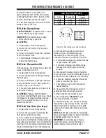
If the resistance is OK, the outlet thermistor 

is good. Proceed to step 4.

 

If the thermistor resistance does not agree 

with the table, replace the outlet thermistor.

4.

  Check P4/P14-3 and P4/P14-6 to 

dryer cabinet ground. If either pin indicates 

continuity to ground (short), replace wiring 

harness; otherwise, proceed to step 5.

5.

  If the preceding steps did not correct the 

problem, replace the CCU.

Temperature Levels Incorrect – 

If no error code 

is displayed and the connections to the thermistor 

are good, check the exhaust temperature value 

at any or all of the temperature levels in question, 

using the 

“timed dry”

 cycle.

1.

  Remove load from dryer and disconnect 

external vent.

2.

  Plug in dryer or reconnect power.

3.

  Run a 

“timed dry” 

cycle of at least 5 

minutes in duration. Select high, medium, 

low, or extra low.

4.

  Using a calibrated temperature probe,  

take a temperature measurement in the center 

of the exhaust outlet. The correct exhaust 

temperatures are as follows:

 

If the temperature is not reached within 

~7 minutes, check voltage level and vent 

blockage, and then retest.

 

If the temperature probe does not agree 

with temperature setting, replace the outlet 

thermistor.

 

If the temperature probe confirms the 

temperature setting, retest at a different 

temperature setting.

TEMPERATURE

SETTING

HEAT TURNS OFF*

°F (°C)

HEAT TURNS ON

°F (°C)

High

155° ± 5°  (68° ± 3°)

Medium

140° ± 5°  (60° ± 3°)

Low

125° ± 5°  (52° ± 3°)

Extra Low

105° ± 5°  (41° ± 3°)

EXHAUST TEMPERATURES

10–15° (6–8°)

below the

heat turn off

temperature

5.

  If the preceding steps did not correct the 

problem, replace the CCU.

Inlet Thermistor

NOTE:

 On the electric dryer, the inlet thermistor 

is part of the high thermostat assembly (see 

Figure 12a, page 14). On the gas dryer, the 

inlet thermistor is located at the top of the drum 

inlet vent (see Figure 17, page 23).
The CCU monitors the inlet temperature using 

the inlet thermistor. The inlet thermistor (along 

with the outlet thermistor) is used to detect air 

flow, and assists in calculating load size.

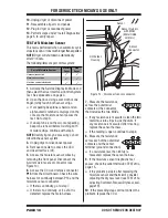
1.

  Unplug dryer or disconnect power.

2.

  Remove console to access the CCU and 

User Interface (UI).

3.

  Remove connector 

P4/P14

 from the CCU  

and measure the resistance between P4/P14-1  

and P4/P14-2 at the connector. The following 

tables (electric & gas) give temperatures and 

the associated resistance values.

NOTE:

 All thermistor resistance measurements 

must be made while dryer is unplugged and 

connector removed from CCU.

 

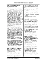
If the resistance is OK, the inlet thermistor 

is good. Proceed to step 4.

 

If the thermistor resistance does not agree 

with the table, replace the inlet thermistor.

TEMP.

°F (°C)

RES. 

RANGE

k ohms

TEMP.

°F (°C)

RES. 

RANGE

k ohms

68°  (20°)

61.2–63.7

131°  (55°)

14.5–15.3

77°  (25°)

49.0–51.0

140°  (60°)

12.1–12.8

86°  (30°)

39.5–41.1

149°  (65°)

10.2–10.7

95°  (35°)

32.0–33.3

158°  (70°)

8.5–9.0

104°  (40°)

26.1–27.2

167°  (75°)

7.2–7.6

113°  (45°)

21.4–22.3

176°  (80°)

6.1–6.5

122°  (50°)

17.6–18.5

ELECT - INLET THERMISTOR RESISTANCE

TEMP.

°F (°C)

RES. 

RANGE

k ohms

TEMP.

°F (°C)

RES. 

RANGE

k ohms

68°  (20°)

57.5–67.6

131°  (55°)

14.1–15.6

77°  (25°)

46.1–53.8

140°  (60°)

11.8–12.9

86°  (30°)

37.4–43.1

149°  (65°)

9.9–10.8

95°  (35°)

30.4–34.7

158°  (70°)

8.4–9.0

104°  (40°)

24.9–28.2

167°  (75°)

7.1–7.6

113°  (45°)

20.5–23.0

176°  (80°)

6.0–6.4

122°  (50°)

16.9–18.9

GAS - INLET THERMISTOR RESISTANCE

TEMP.

°F (°C)

RES. 

RANGE

k ohms

TEMP.

°F (°C)

RES. 

RANGE

k ohms

50° (10°)

19.0–22.0

80° (27°)

8.5–10.5

60° (16°)

14.8–16.8

90° (32°)

6.8–8.8

70° (21°)

11.5–13.5

100° (38°)

5.0–7.0

OUTLET THERMISTOR RESISTANCE

Summary of Contents for W10393006

Page 1: ...roximately 3000V It takes as little as 10V to destroy damage or weaken the main control assembly The new main control assembly may appear to work well after repair is finished but a malfunction may occur at a later date due to ESD stress Use an anti static wrist strap Connect wrist strap to green ground connection point or unpainted metal in the appliance OR Touch your finger repeatedly to a green...

Page 2: ...to standby mode start pause button begin or continue test Pressing button toggles indicator on and off time adjust button pressing the button toggles the Status and LSDs on and off time adjust button pressing button toggles the MSD on and off Figure 1 User Interface Test Press each option button to toggle its respective indicator on and off Some options may not be available on all models drum ligh...

Page 3: ...ER and START and follow the steps below using the same buttons Remember the buttons and the order that the buttons were pressed Within 8 seconds Press and Release the 1st selected button Press and Release the 2nd selected button Press and Release the 3rd selected button Repeat this 3 button sequence 2 more times 3 If the key sequence was entered successfully all indicators on the console are illum...

Page 4: ...ndicators mode exits the Service Diagnostic mode and returns the dryer to standby mode If indicators do not turn off and beep after pressing buttons and rotating the cycle selector knob go to TEST 6 Buttons and Indicators page 19 2 DIAGNOSTIC Console ID Motor Heater and Water Valve if exists Make sure the door is closed and then press the start button The dryer will beep and the motor heater and w...

Page 5: ...ic Display L2 level range 0 to 200 If Gas Display 9as for gas since L2 does not exist 3 Dryer starts L1 detection algorithm Airflow detection starts at this step Motor On Heater On L2 continues to be displayed 4 L1 detection complete CCU calculates L1 to L2 Motor On Heater On Off Once L1 is calculated L1 to L2 is immediately calculated in the CCU 5 Press the START button to cycle through L1 L2 and...

Page 6: ...p and the display shows 8 88 no saved fault codes are present Advancing Through Saved Fault Error Codes Procedure for advancing through saved fault codes Press and release g beep tone g most recent fault the 3rd button code is displayed used to activate Service Diagnostics Repeat g beep tone g second most recent fault code is displayed Repeat g beep tone g third most recent fault code is displayed...

Page 7: ...Sensor Open Indicates the moisture sensor strip is open This fault code will only appear when in the service diagnostic mode See TEST 5 Moisture Sensor page 18 F3E7 Moisture Sensor Shorted Indicates that the moisture sensor strip has shorted This fault code will ONLY appear when in the service diagnostic mode See TEST 5 Moisture Sensor page 18 F4E1 Heater Relay or Connector Problem Indicates no vo...

Page 8: ...uttons Indicators page 19 Drive Belt Belt Switch problem See Test 3 Motor Circuit page 12 Thermal Fuse electric only See Test 4b Thermal Fuse page 17 Door switch problem See Test 7 Door Switch page 20 Motor problem See Test 3 Motor Circuit page 12 CCU problem See Test 1 CCU Power Check page 9 Check installation Verify proper dryer installation Check for L1 and L2 Perform CCU L1 and L2 tests under ...

Page 9: ...th voltmeter set to DC connect black probe to CCU P5 3 ground and red probe to P5 1 5V DC If 5V DC is present go to step 9 If 5V DC is not present go to step 7 7 Unplug dryer or disconnect power Unplug P4 P14 from the CCU Plug in dryer or reconnect power and repeat step 6 If 5V DC returns one of the thermistors has shorted To diagnose thermistors see TEST 4a page 15 If 5V DC is not present go to s...

Page 10: ... it This will be L1 black wire in the wiring diagram See Figure 4a When this is found go to step 5 If neither of the plug terminals have continuity with the left most contact of the terminal block replace the power cord and retest dryer 5 Access the machine electronics without disconnecting any wiring to the CCU 6 With an ohmmeter check for continuity between the L1 terminal of the plug found in s...

Page 11: ... dryer or reconnect power 10 Perform steps under Install Diagnostics page 5 to verify repair GAS DRYER U S and Canadian Installations 1 Unplug dryer or disconnect power 2 Remove the cover plate from the back of the dryer See Figure 5 3 Check that the power cord is firmly connected to the dryer s wire harness See Figure 6 4 Access the machine electronics without disconnecting any wiring to the CCU ...

Page 12: ...worn or damaged drum belt repair as necessary 3 Remove console to access the CCU and User Interface UI 4 Door Switch problems can be uncovered by following procedure under TEST 7 Door Switch page 20 however if this was not done the following can be performed without applying power to the dryer Connect an ohmmeter across CCU P8 3 neutral white wire and P8 4 door tan wire With the door properly clos...

Page 13: ...place the motor 11 Check the belt switch by measuring resistance between the two light blue wires as shown in Figure 11 while pushing up the belt switch pulley If the resistance reading goes from open to a few ohms as pulley arm closes the switch belt switch is good If not replace the belt switch If belt switch is good and there is still an open circuit checkandrepairthemainwiringharness 12 Reasse...

Page 14: ... If the resistance is about 10 Ω go to step 5 If an open circuit is detected or resistance is much greater or less than 10 Ω go to step 4 4 Visually check the wire connections to the thermal cut off high limit thermostat and heater If the connections look good check for continuity across each of these components Refer to Strip Circuit on page 22 Replace the heater if it is electrically open Replac...

Page 15: ...lug dryer or disconnect power 2 Remove console to access the CCU and User Interface UI 3 Remove connector P4 P14 from the CCU and measure the resistance between P4 P14 3 and P4 P14 6 at the connector Refer to Outlet Thermistor Resistance table on page 16 for temperatures and the associated values If the resistance corresponds to the temperature the outlet thermistor is good If the thermistor resis...

Page 16: ...place the CCU Inlet Thermistor NOTE On the electric dryer the inlet thermistor is part of the high thermostat assembly see Figure 12a page 14 On the gas dryer the inlet thermistor is located at the top of the drum inlet vent see Figure 17 page 23 The CCU monitors the inlet temperature using the inlet thermistor The inlet thermistor along with the outlet thermistor is used to detect air flow and as...

Page 17: ... determine if a gas valve coil has malfunctioned Remove harness plugs Measure resistance across the terminals see Figure 13 Readings should match those shown in the following chart if not replace coils 4 Disconnect the ignitor plug from the burner Using an ohmmeter measure the resistance across the ignitor s 2 pin connector Resistance should be 50 500 Ω If resistance readings are outside the range...

Page 18: ... moisture sensor connector see Figure 14 6 Access the CCU and remove connector P13 from the circuit board Check the wire harness for continuity between P13 and the moisture sensor connector If there is continuity go to step 7 If there is no continuity or if a short is detected replace the main harness 7 Measure the resistance across the outermost contacts of the connector that includes the two MOV...

Page 19: ...ome buttons do not light indicators 3 No beep sound is heard None of the indicators or display turn on 1 Unplug dryer or disconnect power 2 Remove console to access the CCU and User Interface UI 3 Visually check that ALL CCU connectors are inserted all the way into the CCU 4 Visually check that the UI connector is inserted all the way into the UI 5 Visually check that the UI and housing assembly i...

Page 20: ...ace the drum lamp and retest If the reading is around 100 150 Ω continue to step 5 5 Remove console to access the CCU and User Interface UI 6 Check Drum Light Harness using an ohmmeter measure the resistance between L1 on the terminal block or AC plug and CCU P8 1 brown wire If the reading is around 100 150 Ω the drum light and harness are OK Continue to step 7 If an open circuit is detected check...

Page 21: ...e and wires are connected to the water valve assembly see Figure 15 Check that the water valve assembly hose is connected to the water nozzle 9 If everything is hooked up and the water still does not dispense Unplug dryer or disconnect power Replace the water valve assembly and retest 10 If the preceding steps did not correct the problem replace the CCU Figure 15 Water Valve Water Nozzle Water Val...

Page 22: ...P RTN INLET TEMP INLET TEMP RTN R W R BK 10 Ω R R BK L1 CYCLE CONTROL UNIT HEATER RELAY K2 COM BK R OUTLET THERMISTOR INLET THERMISTOR 10K Ω 50K Ω THERMAL FUSE HI LIMIT THERMOSTAT THERMAL CUTOFF GAS VALVE ASS Y BU R 50 500 IGNITOR VALVE 1 VALVE 2 FLAME SENSOR MOV BK IG IGR IV 2 1 3 4 5 FS1 1365 25 560 25 1220 50 3V R BK CENTRIFUGAL SWITCH G Y 3M 5M 6M 2M 1M W N R BU R W R W P14 3 P14 6 P14 2 P14 1...

Page 23: ...ocation may vary between models Remove front panel and drum assembly to access Heater Assembly Inlet Thermistor Electric High Limit Thermostat Thermal Cut off Moisture Sensor Strips Thermal Fuse Outlet Thermistor Figure 17 Component Locations SPECIFICATIONS NOTE Refer to Figure 12b page 14 for gas dryer component locations Top Console Voltage 240 V AC 200 260 Elect Dryer 2 phase optimized 208 V AC...

Page 24: ...ESTROY USER INTERFACE CYCLE CONTROL UNIT HEATER RELAY WATER VALVE Voltage References VDD 5V DC VSS GND MAYTAG ELECTRIC DRYER WIRING DIAGRAM Figure 18 IMPORTANT Electrostatic discharge may cause damage to machine control electronics See page 1 for ESD information ...

Page 25: ... DESTROY IMPORTANT Electrostatic discharge may cause damage to machine control electronics See page 1 for ESD information USER INTERFACE CYCLE CONTROL UNIT HEATER RELAY WATER VALVE MAYTAG GAS DRYER WIRING DIAGRAM Figure 19 Voltage References VDD 5V DC VSS GND ...

Page 26: ...PAGE 26 FOR SERVICE TECHNICIAN S USE ONLY DO NOT REMOVE OR DESTROY Notes ...

Page 27: ...st mis sous tension Laisser suffisamment d espace pour pouvoir faire les mesures de tension sans qu il y ait d obstacle Éloigner toutes les autres personnes présentes suffisamment loin de l appareil pour éviter les risques de blessure Toujours utiliser l équipement de test approprié Aprèslesmesuresdetension toujoursdéconnecterlasourcedecourantélectriqueavantdeprocéderauservice IMPORTANT Circuits é...

Page 28: ...poursuivre le test Le fait d appuyer sur le bouton allume et éteint le témoin Bouton time adjust réglage de durée appuyer sur le bouton allume et éteint l état et les chiffres les moins significatifs Bouton time adjust réglage de durée appuyer sur le bouton allume et éteint le chiffre le plus significatif Figure 1 Test de l interface utilisateur Appuyer sur chaque bouton d option pour allumer et é...

Page 29: ... Vérifier que la sécheuse est en mode d attente branchée tous les témoins éteints 2 Sélectionner n importe lequel des trois boutons sauf POWER et START et suivre les étapes ci dessous en utilisant les mêmes boutons Souvenez vous des boutons et de l ordre dans lequel vous avez appuyé sur les boutons En dedans de 8 secondes Appuyer momentanément sur le 1er bouton sélectionné Appuyer momentanément su...

Page 30: ...t chaque témoin du programme correspondant NOTE Une seconde pression sur le bouton power cancel pendant le mode Boutons et témoins de la console fera quitter le mode diagnostic et ramènera la sécheuse au mode d attente Si les témoins ne s éteignent pas et n émettent aucun signal sonore lors des pressions sur les touches ou la rotation du sélecteur de programme passer au TEST nº 6 Boutons et témoin...

Page 31: ...inée Moteur allumé Si électrique Afficher le niveau L2 gamme de 0 à 200 Si gaz Afficher 9as pour gaz puisque L2 n existe pas 3 La sécheuse commence l algorithme de détection de L1 La détection de la circulation d air commence à cette étape Moteur allumé Élément chauffant allumé L2 continue à être affiché 4 Détection de L1 terminée Le MCP calcule L1 à L2 Moteur allumé Élément chauffant allumé étein...

Page 32: ...s deux méthodes listées ci dessous Appuyer pendant 5 secondes sur le 1er bouton utilisé pour activer le mode de diagnostic de service Appuyer une ou deux fois sur le bouton power conformément à la procédure de diagnostic récent Si chaque pression du 3e bouton cause le triple bip et l afficheur indique 8 88 aucun code d anomalie n a été mémorisé Progresser parmi les codes d anomalie codes d erreur ...

Page 33: ...umidité Ce code d anomalie apparaîtra SEULEMENT en mode de diagnostic de service Voir TEST nº 5 Capteur d humidité page 44 F3E7 Capteur d humidité court circuit Indique un court circuit affectant le capteur d humidité Ce code d anomalie apparaîtra SEULEMENT en mode de diagnostic de service Voir TEST nº 5 Capteur d humidité page 44 F4E1 Problème sur le relais du chauffage ou sur un connecteur Indiq...

Page 34: ... 3 Circuit du moteur page 37 Fusible thermique électrique seulement Voir Test nº 4b Fusible thermique page 43 Problème sur le contacteur de la porte VoirTest nº 7 Contacteur de la porte page 46 Problème sur le moteur Voir Test nº 3 Circuit du moteur page 37 Problème sur le MCP VoirTestnº1 ContrôledelatensionduMCP page35 Contrôler l installation Vérifier que l installation de la sécheuse est correc...

Page 35: ... nº 2 Connexions d alimentation page 36 6 MCP 5V CC Exécuter les contrôles de tension suivants à l intérieur du connecteur P5 NE PAS COURT CIRCUITER LES BROCHES ENSEMBLE Avec un voltmètre réglé sur courant continu DC brancher la sonde noire à P5 3 mise à la terre et la sonde rouge à P5 1 5 V CC S il y a une tension de 5 V CC passer à l étape 9 S il n y a pas une tension de 5 V CC passer à l étape ...

Page 36: ...se que la tension de la prise de courant est bonne SÉCHEUSE ÉLECTRIQUE 1 Débrancher la sécheuse ou déconnecter la source de courant électrique 2 Retirer le couvercle à l arrière de la sécheuse Voir Figure 3 3 Accéder aux composants électroniques de la machine sans débrancher de câblage allant vers le MCP 4 Avec un ohmmètre contrôler la continuité entre les broches L1 et N de la fiche de branchemen...

Page 37: ...rdon d alimentation selon les indications de la Figure 7 S il y a un circuit ouvert remplacer le cordon d alimentation Sinon passer à l étape 6 6 D une manière similaire vérifier la continuité entre la broche L1 de la fiche de branchement et la broche P9 2 conducteur noir sur le MCP S il y a continuité passer à l étape 8 S il n y a pas de continuité contrôler la continuité sur le cordon d alimenta...

Page 38: ... circuit du moteur est acceptable Remplacer le MCP Sinon passer à l étape 6 6 Contrôler le câblage et les composants dans le chemin entre ces points de mesure en se référant au schéma de câblage approprié gaz ou électrique en page 51 ou 52 SÉCHEUSE ÉLECTRIQUE SEULEMENT Vérifier le fusible thermique Voir TEST nº 4b Fusible thermique page 43 TOUTES LES SÉCHEUSES Passer à l étape 7 ci dessous pour te...

Page 39: ...ur la broche 3 du contacteur noir du moteur d entraînement Si la résistance mesurée passe de l infini à quelques ohms lors de la fermeture du contacteur par le bras de poulie le contacteur du tensionneur de la courroie est en bon état Sinon remplacer le contacteur de la courroie Si le contacteur de la courroie est en bon état et s il y a toujours un circuit ouvert vérifier et réparer le câblage 12...

Page 40: ...ément chauffant le thermostat de limite haute et le coupe circuit thermique fonctionnent 1 Débrancher la sécheuse ou déconnecter la source de courant électrique 2 Retirer le panneau avant et l ensemble du tambour pour accéder aux composants électroniques de la machine 3 À l aide d un ohmmètre et en consultant les schémas de circuits ou le schéma de câblage mesurer la résistance entre le conducteur...

Page 41: ...blème vérifier le contacteur centrifuge avant de remplacer le MCP 8 Réassembler tous les pièces et panneaux 9 Brancher la sécheuse ou reconnecter la source de courant électrique 10 Exécuter les étapes sous Diagnostic de l installation page 31 pour vérifier la réparation Impossibilité d arrêt du chauffage TOUTES LES SÉCHEUSES 1 Débrancher la sécheuse ou déconnecter la source de courant électrique 2...

Page 42: ...C Haute 155 5 68 3 Moyenne 140 5 60 3 Basse 125 5 52 3 Très basse 105 5 41 3 Températures au point de décharge 10 15 6 8 au dessous du point d interruption du chauffage TEST nº 4a Thermistances NOTE Consulter le schéma des circuits en page 49 pour diagnostiquer les thermistances d entrée et de décharge Thermistance de décharge sortie Le MCP assure un suivi de la température dans le circuit de déch...

Page 43: ...ce d entrée est en bon état Passer à l étape 4 Si la résistance de la thermistance ne correspond pas aux valeurs indiquées dans le tableau remplacer la thermistance d entrée 4 Contrôler la résistance entre P4 P14 1 et P4 P14 2 et la mise à la terre de la sécheuse Si l une des broches indique une continuité à la terre court circuit remplacer le câblage sinon passer à l étape 5 5 Si les étapes précé...

Page 44: ...s du capteur Commande électronique de la machine 4 Débrancher la fiche de l allumeur du brûleur Utiliser un ohmmètre pour mesurer la résistance à travers le connecteur à deux broches de l allumeur La valeur de la résistance doit être contenue entre 50 et 500 Ω Si la valeur de la résistance mesurée se situe en dehors de cette gamme ou est infinie remplacer l allumeur Si la valeur de la résistance m...

Page 45: ...mentation électrique NOTE S il n y a pas d activité utilisateur pendant 20 secondes ou si un bouton autre que start pause ou dryness level est enfoncé le réglage de séchage est ramené à sa configuration antérieure 4 Appuyer à tout moment sur le bouton power pour annuler les changements et quitter ce mode TEST nº 6 Boutons et témoins On exécute ce test lorsqu une des situations suivantes survient d...

Page 46: ...ic Contacteur de la porte Lampe du tambour pour vérifier la réparation Les témoins et l afficheur ne s allument pas 1 Débrancher la sécheuse ou déconnecter la source de courant électrique 2 Retirer la console pour accéder au MCP et à l interface utilisateur IU 3 Vérifier visuellement que TOUS les connecteurs du MCP sont complètement insérés dans le MCP 4 Vérifier visuellement que le connecteur de ...

Page 47: ... du tambour et refaire le test S il n y a pas une tension de 120 V CA remplacer le MCP 8 Débrancher la sécheuse ou déconnecter la source de courant électrique 9 Réassembler tous les pièces et panneaux 10 Exécuter les étapes sous Diagnostic de l installation page 31 pour vérifier la réparation TESTnº9 Électrovanned admissiond eau modèleàvapeur Activer le mode de diagnostic de service et sélectionne...

Page 48: ...urce de courant électrique Remplacer l électrovanne d admission d eau et tester de nouveau 10 Si les étapes précédentes ne résolvent pas le problème remplacer le MCP Reconfiguration des modificateurs et des options à la configuration d usine par défaut Pour restaurer toutes les options et les modificateurs aux valeurs d usine par défaut sélectionner le programme de séchage minuté et appuyer ensuit...

Page 49: ...TEMP D ENTRÉE TEMP D ENTRÉE RET R BL R N 10 Ω R R N L1 COM N R 10K Ω 50K Ω ENSEMBLE D ÉLECTROVANNE À GAZ BU R 50 500 ALLUMEUR ÉLECTROV 1 ÉLECTROV 2 DÉTECTEUR DE FLAMME MOV N IG IGR IV 2 1 3 4 5 FS1 1365 25 560 25 1220 50 3V R N VE JA 3M 5M 6M 2M 1M BL N R BU R BL R BL P14 3 P14 6 P14 2 P14 1 NF NO N O CONTACTEUR DE LA PORTE MODÈLE RET MODÈLE P14 4 P14 5 N N UN CONDUCTEUR EST NÉCESSAIRE POUR LES SÉ...

Page 50: ...ITE Blanc Blanc 123 45 Contacteur centrifuge moteur Électrovanne à gaz sécheuse à gaz Contacteur du moteur d entraînement enfichable Retirer la console supérieure pour accéder Interface utilisateur IU Module de commande de programme MCP Retirer le panneau arrière pour accéder Thermistance d entrée Gaz Lampe du tambour Buse d introduction d eau Modèle à vapeur Électrovanne d admission d eau Modèle ...

Page 51: ...ION D EAU NEUTRAL NEUTRE W BL T TAN G Y VE JA LT BU BU CL BK W N BL Y R JA R THERMAL FUSE FUSIBLE THERMIQUE G Y VE JA Y R JA R R R R R R R R R R R MOISTURE SENSOR CAPTEUR D HUMIDITÉ OUTLET THERMISTOR THERMISTANCE DE DÉCHARGE INLET THERMISTOR THERMISTANCE D ENTRÉE BU BU NC NF NO DOOR SWITCH CONTACTEUR DE LA PORTE W BL W BL BELT SWITCH CONTACTEUR DU TENSIONNEUR DE COURROIE DRIVE MOTOR 1 3 H P MOTEUR...

Page 52: ... NEUTRAL NEUTRE DOOR PORTE GND MASSE MOTOR MOTEUR MTR CS MTR CC MOIST HUMIDITÉ MOIST RTN RET HUMIDITÉ MODEL MODÈLE MODEL RTN RET MODÈLE OUTLET TEMP TEMP DÉCHARGE OUTLET TEMP RTN TEMP DÉCHARGE RET INLET TEMP TEMP D ENTRÉE INLET TEMP RTN TEMP D ENTRÉE RET TF1 TF2 THERMAL FUSE FUSIBLE THERMIQUE R R BK N R R HEATER RELAY RELAIS CHAUFFAGE HEATER V ÉLÉMENT CHAUFFANT V HEATER RTN RET CHAUFFAGE BK N USER ...

Reviews: