background image

113430 - 9

Telephone: (641) 787-7000

13

Domestic Type I (MDG31, MDG51 Only)

!

!

!

!

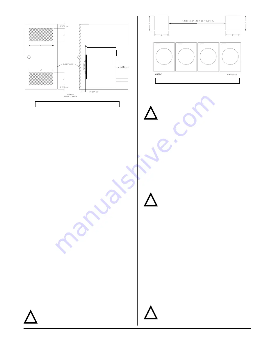
A = 6-inches (15.24 cm)

 B = 24-inches (60.96 cm)

EXAMPLE: For MDG51, 2 unrestricted openings measuring
6-inches by 24-inches (15.24 cm by 60.96 cm) are acceptable.
If a closet door is installed: unobstructed air openings are
required.  The air openings shall be located 3-inches
(7.62 cm) from the lower opening (above floor level) and upper
opening (below ceiling).  The total free area of the air openings
in the door shall not be less than 179 inch

2

 (1154.836 cm

2

)

for MDG31; and 293 inch

2

 (1890.319 cm

2

) for MDG51.

Louvered doors with equivalent air openings are acceptable.
No other fuel-burning appliance shall be installed in the same
closet as the dryer.

Fresh Air Supply Requirements _______

When the dryer is operating, it draws in room air, heats it,
passes this air through the tumbler, and exhausts it out of the
building.  Therefore, the room air must be continually
replenished from the outdoors.  If the make-up air is
inadequate, drying time and drying efficiency will be adversely
affected.  Ignition problems and sail switch “fluttering”
problems may result, as well as premature motor failure from
overheating.  The dryer must be installed with provisions for
adequate combustion and make-up air supply.
Air supply (make-up air) must be given careful consideration
to ensure proper performance of each dryer.  As a general
rule, an unrestricted air entrance from the outdoors of 110
inch

2

 (710 cm

2

) is required for each MDG77, 90 inch

2

 (580

cm

2

) for each MDG51, 55 inch

2

 (354 cm

2

) for each MDG31.

(Based on 1 inch

2

 [6.5 cm

2

] per 1,000 Btu [252 kcal].)

It is not necessary to have a separate make-up air opening
for each dryer.  Common make-up air openings are
acceptable.  However, they must be set up in such a manner
that the make-up air is distributed equally to all the dryers.
To compensate for the use of registers or louvers used over
the openings, this area must be increased by approximately
33%.  Make-up air openings should not be located in an area
directly near where exhaust vents exit the building.
Allowances must be made for remote or constricting
passageways or where dryers are located at high altitudes
or predominantly low pressure areas.

Note

Component failure due to dry cleaning solvent
fumes will void the warranty.

A = 10-inches (25.4 cm)

 B = 11-inches (27.94 cm)

EXAMPLE: For a bank of 4 MDG31 dryers, 2 unrestricted
openings measuring 10-inches by 11-inches (25.4 cm by
27.94 cm) are acceptable.

Important

Make-up air must be free of dry cleaning solvent
fumes.  Make-up air that is contaminated by dry

cleaning solvent fumes will result in irreparable damage to
the motors and other dryer components.

Exhaust Requirements ________________

Exhaust ductwork should be designed and installed by a
qualified professional.  Improperly sized ductwork will create
excessive back pressure, which results in slow drying,
increased use of energy, and shutdown of the burner by the
airflow (sail) switch, burner hi-limits, or lint chamber hi-limit
protector thermostat.  The dryer must be installed with a proper
exhaust duct connection to the outside.
The dryer shall not be exhausted into any gas vent, chimney,
wall, ceiling or concealed space of a building.

Caution

This dryer produces combustible lint and must be
exhausted to the outdoors.

Improperly sized or installed exhaust ductwork can create
a potential fire hazard.

The ductwork should be laid out in such a way that the
ductwork travels as directly as possible to the outdoors with
as few turns as possible.  There should be a minimum
6-inch (15.24 cm) clearance between the back guard and the
first bend in the ductwork for ease of servicing.  Single or
independent dryer venting is recommended.  It is suggested
that the use of 90° turns be avoided; use 30° and/or 45°
bends instead.  The radius of the elbows should preferably
be 1-1/2 times the diameter of the duct.  All ductwork should
be smooth inside with no projections from sheet metal
screws or other obstructions, which will collect lint.  When
adding ducts, overlap the duct being connected.  All ductwork
joints must be taped to prevent moisture and lint from
escaping into the building.  Back draft dampers must be
installed in all commonly ducted systems.  Inspection doors
should be installed at strategic points in the exhaust ductwork
for periodic inspection and cleaning of lint from the ductwork.

Important

It is recommended that exhaust or booster fans
not be used in the exhaust ductwork system.

Summary of Contents for MDG31

Page 1: ...upplier AVERTISSEMENT Assurez vous de bien suivre les instructions données dans cette notice pour réduire au minimum le risque d incendie ou d explosion ou pour éviter tout dommage matériel toute blessure ou la mort Ne pas entreposer ni utiliser d essence ni d autres vapeurs ou liquides inflammables à proximité de cet appareil ou de tout autre appareil QUE FAIRE SI VOUS SENTEZ UNE ODEUR DE GAZ Ne ...

Page 2: ..._______________________________________________ MODELNO _________________ DISTRIBUTOR S NAME ____________________________________________________________________________________ Serial Number s ________________________________________________________________________________________ _______________________________________________________________________________________________________ _____________...

Page 3: ...llowed to play on or near the dryer s Children should be supervised if near dryer s in operation Under no circumstances should the dryer door switch es lint door drawer switch es or heat safety circuit s ever be disabled The dryer must never be operated with any of the back guards outer tops or service panels removed Personal injury or fire could result The dryer must never be operated without the...

Page 4: ... similarly textured rubber materials Drying in a heated tumbler may damage plastics or rubber and also may be a fire hazard A program should be established for the inspection and cleaning of lint in the burner area exhaust ductwork and area around the back of the dryer The frequency of inspection and cleaning can best be determined from experience at each location Warning The collection of lint in...

Page 5: ..._________ ___________________________________________ ___________________________________________ ___________________________________________ ___________________________________________ ___________________________________________ ___________________________________________ ___________________________________________ ___________________________________________ ______________________________________...

Page 6: ...SSED AIR CONNECTION N A COMPRESSED AIR VOLUME N A INLET PIPE CONNECTION 1 2 M N P T VOLTAGE AVAILABLE N A APPROXIMATE NET WEIGHT APPROXIMATE SHIPPING WEIGHT AIRFLOW EXHAUST CONNECTION DIAMETER COMPRESSED AIR CONNECTION COMPRESSED AIR VOLUME OVEN SIZE kW Btu hr kcal hr VOLTAGE AVAILABLE N A APPROXIMATE NET WEIGHT APPROXIMATE SHIPPING WEIGHT AIRFLOW STEAM CONSUMPTION OPERATING STEAM PRESSURE EXHAUST...

Page 7: ...113430 9 Telephone 641 787 7000 7 MDG31 Specifications ________________________________________________________________ ...

Page 8: ...m COMPRESSED AIR CONNECTION N A COMPRESSED AIR VOLUME N A INLET PIPE CONNECTION 1 2 M N P T 1 2 F B S P T CE and Australia Only VOLTAGE AVAILABLE N A APPROXIMATE NET WEIGHT APPROXIMATE SHIPPING WEIGHT AIRFLOW EXHAUST CONNECTION DIAMETER COMPRESSED AIR CONNECTION COMPRESSED AIR VOLUME OVEN SIZE kW Btu hr kcal hr VOLTAGE AVAILABLE N A APPROXIMATE NET WEIGHT APPROXIMATE SHIPPING WEIGHT AIRFLOW STEAM ...

Page 9: ...113430 9 Telephone 641 787 7000 9 MDG51 Specifications _________________________________________________________________ ...

Page 10: ... cm COMPRESSED AIR CONNECTION N A COMPRESSED AIR VOLUME N A INLET PIPE CONNECTION 1 2 M N P T 1 2 F B S P T CE and Australia Only VOLTAGE AVAILABLE N A APPROXIMATE NET WEIGHT APPROXIMATE SHIPPING WEIGHT AIRFLOW EXHAUST CONNECTION DIAMETER COMPRESSED AIR CONNECTION COMPRESSED AIR VOLUME OVEN SIZE kW Btu hr kcal hr VOLTAGE AVAILABLE N A APPROXIMATE NET WEIGHT APPROXIMATE SHIPPING WEIGHT AIRFLOW STEA...

Page 11: ...113430 9 Telephone 641 787 7000 11 MDG77 Specifications ______________________________________________________________ ...

Page 12: ... be achieved as noted in this manual refer to Exhaust Requirements section Important The dryer should be located where a minimum amount of exhaust ducting will be necessary The dryer must be installed with adequate clearance for air openings into the combustion chamber Caution This dryer produces combustible lint and must be exhausted to the outdoors Every 6 months inspect the exhaust ducting and ...

Page 13: ...ers are located at high altitudes or predominantly low pressure areas Note Component failure due to dry cleaning solvent fumes will void the warranty A 10 inches 25 4 cm B 11 inches 27 94 cm EXAMPLE For a bank of 4 MDG31 dryers 2 unrestricted openings measuring 10 inches by 11 inches 25 4 cm by 27 94 cm are acceptable Important Make up air must be free of dry cleaning solvent fumes Make up air tha...

Page 14: ...appliance category in accordance with national installation regulations of the country of destination Outside Ductwork Protection To protect the outside end of the horizontal ductwork from the weather a 90 elbow bent downward should be installed where the exhaust exits the building If the ductwork travels vertically up through the roof it should be protected from the weather by using a 180 turn to...

Page 15: ...oper installation will void the warranty Each dryer should be connected to an independently protected branch circuit The dryer must be connected with copper wire only Do not use aluminum wire which could cause a fire hazard The copper conductor wire cable must be of proper ampacity and insulation in accordance with electric codes for making all service connections Note The use of aluminum wire wil...

Page 16: ...r or the dryer can be hard wired directly to the service breaker panel In both cases a strain relief must be installed where the wiring enters the dryer For CE Models Only The means for disconnection from the supply must be incorporated into wiring having a minimum contact separation of 3 0 mm in all poles Single Phase 1ø Wiring Connections Hookup The electrical input connections are made into the...

Page 17: ...e or disconnect the dryer from supply as noted can cause irreparable damage to the gas valve voiding the warranty Note The dryer must be isolated from the gas supply piping system by closing its individual manual shutoff valve during any pressure test of the gas supply system at test pressures equal to or less than 1 2 psig 3 5 kPa for non CE dryers or 50 mb for CE dryers Warning Fire or explosion...

Page 18: ... M3 H 22 3 988 2 6 9 Natural I2L 830 20 35 110 000 32 24 3 753 M3 H 22 3 988 2 9 5 Natural I2ELL 830 15 30 110 000 32 24 3 753 M3 H 22 3 988 2 9 5 Natural I2E 1 000 20 110 000 32 24 3 115 M3 H 31 3 048 2 830 25 110 000 32 24 3 753 M3 H 31 3 048 2 Butane I3 3 175 28 30 110 000 32 24 2 324 kg H 48 1 930 2 Propane I3 2 500 37 110 000 32 24 2 324 kg H 48 1 930 2 Butane I3B P 3 175 28 30 50 110 000 32 ...

Page 19: ...aks with a flame Converting from One Family of Gas to Another ______________________ Warning CE Dryers This appliance must only be operated with the gas type indicated on the dryer s data plate If the appliance is converted gas type changed a data plate amendment must be obtained from Maytag dryer s serial number is required to purchase a conversion kit Important Any burner changes or conversions ...

Page 20: ...wing 3 options the conversion to be performed Converting from unregulated L P to regulated natural gas use a flat screwdriver to remove the cap with blocking pin and install the regulator vent cap from the kit P N 140415 Locate the gas train and disconnect the union 3 electrical plugs and the gas train mounting screws from the burner Carefully slide the gas train out of the gas train enclosure The...

Page 21: ...tions or codes It is the installer s or owner s responsibility to see that the required water pressure pipe size or connections are provided The manufacturer assumes no responsibility if the fire suppression system is not connected installed or maintained properly Converting from unregulated L P to unregulated natural gas no change to the regulator is required Converting from regulated L P to regu...

Page 22: ...ply feed line Electrical Requirements No independent external power source or supply connection is necessary The 24 volt power to operate the fire suppression system is accomplished internally in the dryer from the dryer controls Warning Electrical power must be provided to the dryer at all times If the main electrical power supply to the dryer is disconnected the fire suppression system is inoper...

Page 23: ...ctions is pressed Non Coin Models Microprocessor Controller Computer The L E D display reads READY no cycle in progress Press the letter on the keypad corresponding to the cycle desired e g key D The dryer will then start i e blower tumbler and heat The L E D display will read MANUAL DRYING CYCLE D ___MIN REMAIN Note The dryer can be stopped at any time by pressing the STOP CLEAR key at this time ...

Page 24: ...uidelines in this section are met the dryer will provide many years of efficient trouble free and most importantly safe operation Warning Lint from most fabrics is highly combustible The accumulation of lint can create a potential fire hazard Keep dryer area clear and free from combustible materials gasoline and other flammable vapors and liquids Note Suggested time intervals shown are for average...

Page 25: ... for a particular model 7 Gas Manifold Pressure For Gas Dryers This describes the manifold pressure taken at the gas valve tap CE Label Note Do not obstruct the flow of combustion and ventilation air Check back draft dampers in the exhaust ductwork Inspect and remove any lint accumulation which can cause the damper to bind or stick A back draft damper that is sticking partially closed can result i...

Page 26: ...Part No 113430 9 02 15 08 0 ...

Reviews: