background image

54

w

IrIng

 D

IagraMs

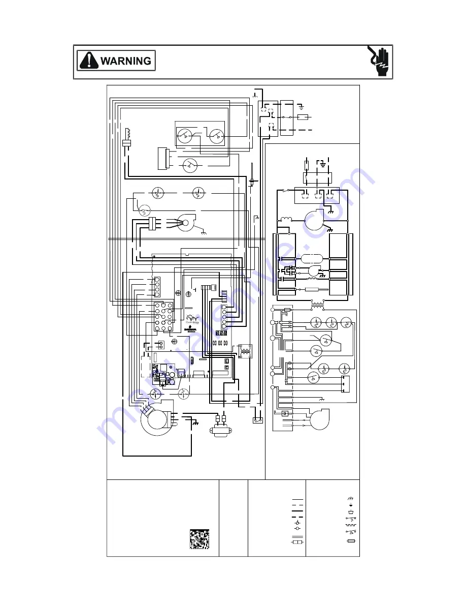
Wiring is subject to change.  Always refer to the wiring diagram on the unit for the most up-to-date wiring.

HIGH VOLTAGE!

D

ISCONNECT


ALL


POWER


BEFORE


SERVICING


OR


INSTALLING


THIS


UNIT

.  

M

ULTIPLE


POWER


SOURCES


MAY


BE


PRESENT

. F

AILURE


TO


DO


SO


MAY


CAUSE


PROPERTY


DAMAGE

PERSONAL


INJURY


OR


DEATH

.

0140F02453-A

FRONT COVER

PRESSURE SWITCH

NO

C

FUSE 3 A

MICRO

TO

PS2 (12)

TR (11)

G

HI

C

TH (4)

24V THERM

OSTAT CON

NECTIONS

VALVE

GAS

TRANSFORMER

HLI (1)

Y

HLO (10)

GND (5)

MVL (13)

NO

W

C

R

CONTROLS

AUTO RESET AUXILIARY LIMIT

LIMIT CONTROLS

MANUAL RESET ROLLOUT

PRESS. SWITCH

HIGH FIRE

C

PSO (7)

SWITCH

LOW FIRE PRESS.

MVH (14)

DEHUM

GND

PS1 (2)

LIMIT CONTROL

AUTO RESET PRIMARY

24 VAC

NO

PM

MVC (8)

INTEGRATED CONTROL MODULE

C

BLWR

AIR

INDOOR

CIRCULATOR

TX (3)

RX (2)

+ VDC (1)

GND (4)

R

TO

MICRO

TO

TO +VDC

EAC

ID

NEUTRAL

WIRING TO UNIT

L

INTEGRATE

D CONTROL 

MODULE

HOT SURFACE

INDUCTOR COIL

GND

BLWR

NEUTRAL

WARNING:

GROUNDED.

OVERCURRENT PROTECTION DEVICE

MUST BE PROPERLY

SWITCH

NEUTRAL

ELECTRONIC

AIR

(ON SOME MODELS)

IGN

IND HI

DISCONNECT

FS

POLARIZED AND

LINE

NEUTRAL

JUNCTION BOX

BLWR

IND LO

N

INDOOR

AIR CLEANER

DOOR

NEUTRAL

INTEGRATE

D CONTROL 

MODULE

TO 115VAC/ 1

Ø /60 HZ POWER SUPPLY WITH

115 VAC

IGNITER

CIRCULATOR

BEFORE SERVICING.

FLAME SENSOR

DISCONNECT POWER

LINE

GND

OR

BR

BK

WH

WH

PU

GY

YL

OR

BR

PK

RD

WH

BK

GY

GN

OR

RD

BK

GY

BL

NO

2

1. SET HEAT ANTICIPATOR ON ROOM THERMOSTAT AT 0.7 AMPS.

PK

WARNING:DISCONNECT

TRANSFOR

MER

40 V

A

PU

GY

N

NO

3

BR

4. UNIT MUST BE PERMANENTLY GROUNDED AND CONFORM TO N.E.C. AND LOCAL CODES.

COLOR CODES:

1

SWITCH

PRESSURE

LOW FIRE

SENSOR

FLAME

GN GREEN

GR

PRESSURE SWITCH

FRONT COVER

C

VAC

TO UNIT MUST BE

1

BL

RD

AND GROUNDED.

1

115

WH

SWITCH (PRESS.)

FIELD SPLICE

FIELD GND

LOW VOLTAGE FIELD

GN

BL

BR

WH

NO

LIMIT CONTROL

AUTO RESET PRIMARY

WH

1

OR

RD RED

GY GRAY

40 kBTU)

CONTROLS (SINGLE CONTROL ON

MANUAL RESET ROLLOUT LIMIT

WH

L

PU

NOTES:

GY

PK

BK

5

SWITCH ASSEMBLY

ID BLOWER TWO-STAGE PRESSURE

OR

WH

SERVICING. WIRING

EQUIPMENT GND

(ON SOME MODELS)

INTERNAL TO

SWITCH

PRESSURE

HIGH FIRE

PROT. DEVICE

INTEGRATED CONTROL

PK

C. USE COPPER CONDUCTORS ONLY.

$

  AT  LEAST 105

   IT MUST BE REPLACED WITH  WIRING MATERIAL HAVING A TEMPERATURE RATING OF

3. IF ANY OF THE ORIGINAL WIRE AS SUPPLIED WITH THE FURNACE MUST BE REPLACED,

PU

PLUG CONNECTION

2

4

BK

C

 DOOR OPEN)

(OPEN WHEN

DOOR SWITCH

COMPARTMENT

BLOWER

SWITCH (TEMP.)

GND

BLOWER

CIRCULATOR

PU  PURPLE

JUNCTION

OR

40 VA

PK PINK

Ø /60 HZ

DISCONNECT

(WHITE-RODGERS)

GAS VALVE

TWO STAGE

2. MANUFACTURER'S SPECIFIED REPLACEMENT PARTS MUST BE USED WHEN SERVICING.

OVERCURRENT

HI VOLTAGE (115V)

CONNECTOR

2 CIRCUIT

LOW VOLTAGE (24V)

YL

GND

VAC

CHASSIS GROUND

2

3

4

IGNITER

SURFACE

HOT

2

GND

BK BLACK

YL

PU

C

INDUCTOR COIL

BL BLUE

C

BLOWER

DRAFT

INDUCED

WH WHITE

PM

BK

24

115 VAC/ 1

OVERCURRENT

BK

BR BROWN

YL YELLOW

3

HI VOLTAGE FIELD

OR ORANGE

HI

TERMINAL

OR

POWER BEFORE

IGNITER

RD

BK

TO

POWER SUPPLY WITH

BURNER COMPARTMENT

PROTECTION DEVICE

PROPERLY POLARIZED

WH

BK

JUNCTION BO

X

GN

GND

GND

PU

BL

 HLI (3)

 HLI (6)

10

6

3

13

4

5

2

7

14

11

15

1

12

8

9

FUSE 3A

CENTER

RIGHT

LEFT

C

RAT

GND
GND

SAT

IGN

IND-HI

IND-LO

IND-N

IGN-N

LI

NE

NEUT

RA

L

DE

Y

G

W

C

R

R

1

2

NA

HUM

CONDEN -SAT

E

EC

M

6

1

6

1

6

1

FS

EAC

1

2

4

2

3

1

3

5

1

4

BL

BK

RD

GY

BK

BL

PU

IN

OUT

CONDENSAT

E

SW

ITCH

(OPTIONA

L)

LIMIT

CONTROL

AUXILIARY

AUTO RESET

BLOWER COMPARTMENT

HARNESS

ECM MTR

BLUETOOTH

BOARD

OPT. HUM.

BR

OPT. HUM.

Summary of Contents for Amana CVC96 BA Series

Page 1: ...ver if there is a direct conflict between existing practices and the content of this manual the precautions listed herein take precedence RECOGNIZE THIS SYMBOL AS A SAFETY PRECAUTION NOTE Please conta...

Page 2: ...te of Massachusetts 19 Condensate Drain Lines Drain Trap 21 Gas Supply and Piping 26 Propane Gas High Altitude Installations 26 Duct Work 30 Electrical Connections 33 Startup Procedure Adjustment 40 N...

Page 3: ...LOSION HAZARD AVERTISSEMENT RISQUE D INCENDIE OU D EXPLOSION Si les consignes de s curit ne sont pas suivies la lettre cela peut entra ner la mort de graves blessures ou des dommages mat riels Ne jama...

Page 4: ...trical connections circulating air temperature rise minimum or maximum CFM WARNING To prevent property damage personal injury or death due to fire do not install this furnace in a mobile home trailer...

Page 5: ...nces In their absence follow the latest edition of the National Fuel Gas Code NFPA 54 ANSI Z223 1 and or CAN CSA B149 1 15 Installation Codes local plumbing or waste water codes and other applicable c...

Page 6: ...hylene printing inks chlorinated waxes or cleaners paint removers chlorine based swimming pool chemicals varnishes water softening chemicals hydrochloric acid carbon tetrachloride cements and glues de...

Page 7: ...nit install the furnace upstream or in parallel with the cooling coil unit Premature heat exchanger failure will result if the cooling unit is placed ahead of the furnace For vertical upflow or downfl...

Page 8: ...rmining the combustion air requirements for the appliances Clearance in accordance with local installation codes the requirements of the gas supplier and the manufacturer s installation instructions D...

Page 9: ...t hood relief opening after 5 minutes of main burner operation Use the flame of a match or candle 8 If improper venting is observed during any of the above tests the venting system must be corrected i...

Page 10: ...cun des appareils raccord s au syst me de ventilation au moment de sa mise en marche alors que tous les autres appareils raccord s au syst me de ventilation ne sont pas en marche 1 Sceller toutes les...

Page 11: ...n the U S A and Canada Manufacturers Installation instructions for these products must be followed These products have specific instructions for installing joining and terminating Do not mix materials...

Page 12: ...flue products Additionally it is the responsibility of the installer to ensure that all piping and connections possess adequate structural integrity and support to prevent flue pipe separation shiftin...

Page 13: ...e or the anticipated snow level and be at least 12 inches from any vertical wall including any anticipated snow build up A vent termination shall not terminate over public walkways or over an area whe...

Page 14: ...B149 1 15 takes precedence over the preceding termination description Canadian Vent Pipe Combustion Air Pipe Requirements All installations in Canada must conform to the requirements of CAN CSA B149 1...

Page 15: ...N A 3 151 144 137 130 123 116 109 102 2 120 115 110 105 100 95 90 85 3 185 178 171 164 157 150 143 136 2 85 80 75 70 65 60 55 50 3 168 161 154 147 140 133 126 119 2 40 35 30 25 20 15 10 5 3 120 113 10...

Page 16: ...flange to the cabinet CAUTION Be sure not to damage internal wiring or other components when reinstalling coupling and screws Figure 11 WARNING The rubber elbow is not designed to support a load When...

Page 17: ...8 measured from the front edge of the cabinet in line with the knock out To use the alternate combustion air location 1 Remove screws and combustion air flange from cabinet 2 Insert cabinet plug in u...

Page 18: ...nnection of pipes to the furnace refer to the Vent Flue Pipe and Combustion Pipe Standard Furnace Connections or Alternate Furnace Connections 90 ELBOWS 3 24 Alternate Horizontal Vent Termination Dual...

Page 19: ...e Side Wall Vent Kit p n 0170K00000S or 0170K00001S for installation specifications Vertical Installation H orizontal Installation Figure 21 SPECIAL INSTRUCTIONS FOR PRODUCTS INSTALLED IN THE STATE OF...

Page 20: ...equipment is to be installed In addition the installing plumber or gasfitter shall observe that a battery operated or hard wired carbon monoxide detector with an alarm is installed on each additional...

Page 21: ...rain Exiting Right Side 1 Locate and Install the 45 pipe hose drain coupling from the outside of the cabinet barbed end goes in the cabinet through hole in the right side of the cabinet and secure wit...

Page 22: ...lied Drain section for instructions on field supplied nstalled drain on outlet of furnace trap Upflow model installed horizontally with left side down Minimum 5 clearance is required for the drain tra...

Page 23: ...he clamps from the two drain tubes on the trap 2 Remove the two screws holding the drain trap to the blower deck 3 Remove the trap and hoses from the blower deck 4 Remove the two plugs from the left s...

Page 24: ...holes with the pre drilled holes in the furnace and secure with 2 screws removed in step 2 7 Refer to Field Supplied Drain section for instructions on field supplied installed drain on outlet of furna...

Page 25: ...end of hose 4 on the side port of vent drain elbow and secure with a gold clamp 10 Insert a diameter PVC pipe factory installed into hose 4 and secure with a gold clamp 11 Insert the non grommet end...

Page 26: ...fice size Propane Gas Conversion WARNING Possible property damage personal injury or death may occur if the correct conversion kits are not installed The appropriate kits must be applied to ensure saf...

Page 27: ...utoff valve and the furnace Tighten all joints securely Connection method must be in compliance with all local and national codes US National Fuel Gas Code NFGC NFPA 54 2015 ANSI Z223 1 2015 and the I...

Page 28: ...against physical and thermal damage when installed Ensure aluminum alloy tubing and connectors are coated to protect against external corrosion when in contact with masonry plaster or insulation or su...

Page 29: ...urnace manifold with all gas appli ances in operation Maintaining proper gas pressure depends on three main factors 1 Vaporization rate depending on temperature of the liquid and wetted surface area o...

Page 30: ...check for closed dampers registers undersized and or oversized poorly laid out duct work NOTE The temperature rise of the furnace must be within the temperature rise range listed on the furnace ratin...

Page 31: ...ed in either the central return register or in the return air duct work Bottom Return Air Opening Upflow Models The bottom return air opening on upflow models utilizes a lance and cut method to remove...

Page 32: ...greater than 25 W C In some installations the minimum filter size required will not lend itself to a filter installation on the side of the furnace The installation of a centrally installed air clean...

Page 33: ...ified on the unit rating plate Power supply to the furnace must be NEC Class 1 and must comply with all applicable codes The furnace must be electrically grounded in accordance with local codes or in...

Page 34: ...le plugs WARNING To prevent personal injury or death due to electric shock disconnect electrical power before installing or servicing this unit Line voltage connections can be made through either the...

Page 35: ...g operation make system menu adjustments add site visit notes and run system testing of all operational modes heat cool fan directly from the phone The phone application is also capable of directly up...

Page 36: ...stem will remain in charge mode high speed for 60 minutes before timing out c The installer must manually shut off charge mode once complete 2 Two stage outdoor units using the CoolCloud HVAC applicat...

Page 37: ...0 for high stage operation 6 Confirm thermostat heating and cooling calls function properly with equipment Quick Start Guide for Gas Heat Only Setup No Outdoor Unit EXTREMELY IMPORTANT The furnace onl...

Page 38: ...and to then permanently select options within those menus NOTE After scrolling to the desired option within a menu that option may be flashing on the 7 segment displays This indicates the option has...

Page 39: ...airflow from the HVAC system to function accordingly 1 Make sure the installed 24VAC thermostat is capable of controlling the accessory or accessories 2 Connect the appropriate accessory control wires...

Page 40: ...five minutes then smell for gas Be sure check near the floor as some types of gas are heavier than air 7 If you smell gas after five minutes immediately follow the safety instructions in the Safety C...

Page 41: ...lve and disconnect manometer Reinstall plug before turning on gas to furnace 6 Turn OFF any unnecessary gas appliances stated in step three Gas Manifold Pressure Measurement and Adjustment CAUTION To...

Page 42: ...l variations in gas pressure should be made by adjusting the gas valve pressure regulator The manifold pressure must be measured with the burners operating To measure and adjust the manifold pressure...

Page 43: ...is rate it would take 46 seconds to consume one cu ft of gas 3600 46 78 This tells us that in one hour the furnace would consume 78 cu ft of gas The typical value range for 1 cu ft of natural gas is a...

Page 44: ...onditions Igniter warm up begins upon Inducer draft blower step to low speed and presence of closed low stage pressure switch contacts Gas valve opens at end of igniter warm up period delivering gas t...

Page 45: ...which uses the principle of flame rectification to determine the presence or absence of flame Burner Flame Figure 65 TROUBLESHOOTING Electrostatic Discharge ESD Precautions NOTE Discharge body s stat...

Page 46: ...cket near furnace MAINTENANCE Annual Inspection WARNING To avoid electrical shock injury or death disconnect electrical power before performing any maintenance If you must handle the igniter handle wi...

Page 47: ...ordered by description Parts are available from your distributor Functional Parts List Gas Valve Blower Motor Gas Manifold Blower Wheel Natural Gas Orifice Blower Mounting Bracket Propane Gas Orifice...

Page 48: ...rflow Off Delay Time default 60 seconds Hnd Heat Pump Heating Airflow On Delay Time default 5 seconds H P Select the range that includes the desired compressor RPS for inverter heating operation See i...

Page 49: ...ngle Stage single stage non comm units AC1 Compressor Cooling Low Stage communicating units AC2 Compressor Cooling High Stage communicating units dF1 Defrost Low Stage Gas Heat dF2 Defrost High Stage...

Page 50: ...ata set is correct for the specific model re populate data using correct memory card if required Furnace operates at reduced performance Airflow delivered is less than expected E Circulator blower mot...

Page 51: ...and sensor if coated and or oxidized Check flue piping for blockage proper length elbows and termination Verify proper induced draft blower performance Furnace fails to operate EE1 Low stage pressure...

Page 52: ...Verify and correct unit ground wiring if needed Check igniter output from control replace if necessary Furnace fails to operate on high stage furnace operates normally on low stage Induced draft blow...

Page 53: ...blower compartment Check filters and ductwork for blockage clean filters or remove obstruction Check circulator blower speed and performance correct speed or replace blower motor if necessary Tighten...

Page 54: ...ME GN GREEN GR PRESSURE SWITCH FRONT COVER C VAC TO UNIT MUST BE 1 BL RD AND GROUNDED 1 115 WH SWITCH PRESS FIELD SPLICE FIELD GND LOW VOLTAGE FIELD GN BL BR WH NO LIMIT CONTROL AUTO RESET PRIMARY WH...

Page 55: ...55 THIS PAGE IS INTENTIONALLY LEFT BLANK...

Page 56: ...ebec residents to register their product does not diminish their warranty rights For Product Registration please register as follows Goodman Brand products https www goodmanmfg com product registratio...

Reviews: