


Installation and Operational Instructions for
EAS
®
-XT clutch Type 475._24._ Sizes 3 – 6
(B.4.75.2.GB)
10/11/2010 TK/VG/SU
Chr. Mayr GmbH + Co. KG
Tel.: 08341 / 804-0
Eichenstraße 1
Fax: 08341 / 804-421
D-87665 Mauerstetten
http://www.mayr.de
Page 3 of 8
Germany
E-Mail:
Guideline on Torque Adjustment
In order to avoid inadvertent disengagement of the overload
clutch, we recommend an adjustment factor of 1,3 on the max.
operating torque.
The max. operating torque is the highest torque occurring on the
overload clutch.
Clutch Engagement After Overload
(Figs. 1 and 2)
Wear ear protection!
During engagement, a noise level of over 100
dB(A) is possible, depending on the clutch size.
Screw the engagement tool (32) with both
hands hard into the control element (3) thread,
until only the red part of the tool is still visible.
The hub (1) and the control element (3) are now
centred.
Then loosen the engagement tool (32) by a full rotation. In
order to re-engage the clutch, manual turning between the
input and the output (max. c. 15°) is usually neces sary.
The turning direction is irrelevant.
However, if the engagement element constellation is
unfavourable, re-engagement can already take place as the
engagement tool (32) is being screwed in. Therefore, always
hold the engagement tool (32) with both hands when
screwing it into the clutch => Danger of backlash!
When turning manually, the radial bores in the adjusting nut (4)
and the output flange (19) serve as contact points for the hook
wrench, as can be seen in Fig. 2.
CAUTION
During manual turning, keep a safe distance
away from the engagement tool (32)!
=> Danger of backlash!
After re-engagement has taken place, the
engagement tool (32) must be completely
removed from the clutch!
Fig. 2
Installation Preparations (Customer-side)
Bore or shaft surface quality:
Ra = 0,8 µm acc. DIN 4762.
Standard bore or shaft tolerances: G7 / h6.
Standard tolerance of the keyway: JS9.
For torque adjustment in installed condition, the minimum
distance dimension "C" must be maintained (possibly via a
distance ring, see page 5 / Fig. 12 and Table 3).
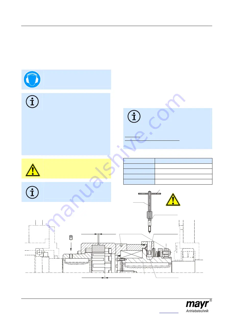
Mounting onto the Shaft (Figs. 1 and 2)
The flexible coupling part (Items 26 - 30) is a simple plug-in
coupling.
Both clutch/coupling parts (the flexible part and the
EAS
®
-XT part) are mounted onto the shaft ends and
secured axially (e.g. using a press cover and/or an
adjusting screw).
After this, both clutch/coupling parts can simply be plugged
together.
Avoid tension on the flexible coupling part (26).
Please observe the inspection dimension "S"
(Table 1).
For joining the clutch/coupling parts an axial installation force is
required. The amount of force required can be reduced by
lightly greasing the intermediate ring (26).
Important!
Use polyurethane-compatible lubricants.
To make installation easier, parts of the clutch can be heated to
max. +100 °C.
Table 1
Size
Inspection dimension "S"
3
3,5 ±1,5 mm
4
4 +2/-1 mm
5
5,5 +2,5/-1,5 mm
6
8 ± 2,5 mm
Danger of backlash
on
engagement
Threaded hole for
engagement tool
Bore for
hook wrench
EAS
®
- XT - part
Flexible part
Inspection dimension "S"
(Item 3)
(Items 19 and 4)
Clutch engaged
Item 1
Painted
red
Engagement tool
Item 32


