Installation and Operational Instructions for EAS
®
-compact
®
Ratchetting clutch, Type 49_._ _0._
Sizes 01 to 3
Synchronous clutch, Type 49_._ _5._
Sizes 01 to 3
(B.4.14.EN)
17/03/2021 TK/NU/GC/GF/SU
Chr. Mayr GmbH + Co. KG
Eichenstraße 1, D-87665 Mauerstetten, Germany
Phone: +49 8341 804-0, Fax: +49 8341 804-421
Page 11 of 22
Output Elements Installation
The output element is centred on a deep groove ball bearing (6)
(tolerance H7/h5) and bolted together with the pressure flange
(2).
Please observe the maximum permitted screw-
in depth in the pressure flange (2) as well as
the connection dimensions “a” and “e” for the
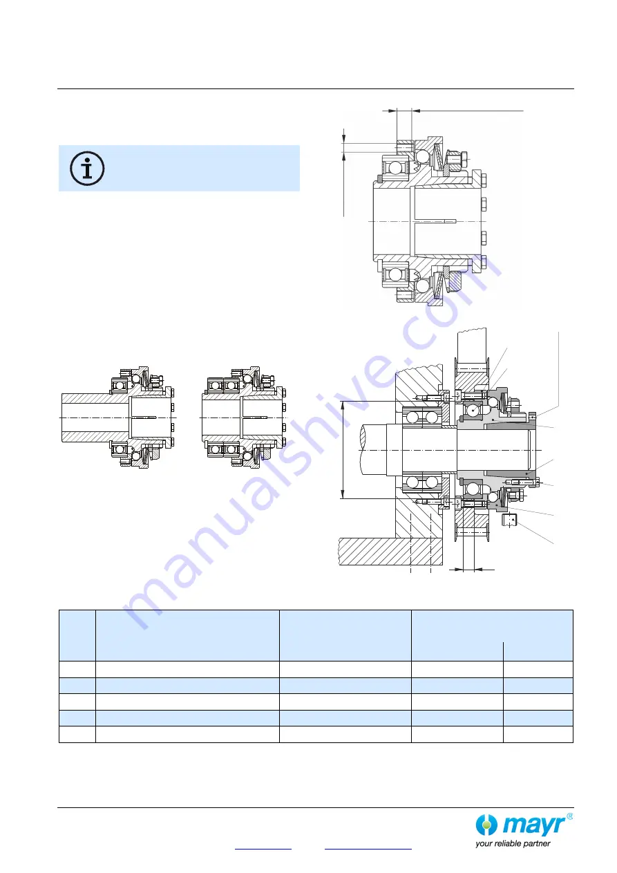
output elements, see Figs. 3 or 4 and Table 16.
If the resulting radial force from the output element is anywhere
near the centre of the ball bearing (6) and under the max.
permitted radial load acc. Table 4, an additional bearing for the
output element is not necessary.
No appreciable axial forces (see Table 4) should be
transferred from the output element onto the clutch
pressure flange (2).
The EAS
®
-compact
®
with a long protruding hub (Type
490._ _ _.1 / Fig. 2) is recommended for extremely wide output
elements, or for elements with small diameters. On very small
diameters, the output element is screwed together with the clutch
pressure flange (2) via a customer-side intermediate flange.
In case of increased radial forces, a 2-bearing design (Type
490._ _ _.2 / Fig. 2) should be used.
Example:
Type 490.61_.1
Type 490.61_.2
Fig. 2
Ball bearings, needle bearings or bearing bushings are suitable
as bearings for the output element, depending on the installation
situation and the installation space.
Please ensure that the output element bearing is designed
as a fixed bearing (Fig. 4).
Fig. 3
Fig. 4
Table 16
Size
Thread in the pressure flange (Fig. 3)
with required screw quality
and tightening torque for the customer-side
screw connection
Max. screw-in depth [mm]
in the pressure flange (Fig. 3)
Connection dimensions [mm]
(Fig. 4)
a
+0.1
e
H7
h5
01
8 x M4 / 8.8 / 2.6 Nm
6
5
47
0
8 x M5 / 8.8 / 5.1 Nm
7
7
62
1
8 x M6 / 8.8 / 9 Nm
9
9
75
2
8 x M6 / 12.9 / 16 Nm
10
10
90
3
8 x M8 / 12.9 / 40 Nm
12
10
100
2
1
6
13
3
11
12
a
e
Tap
p
e
d
e
x
tr
a
c
ting
h
o
le
Maximum screw-in depth
in the pressure flange
Thr
e
a
d
in
p
re
s
s
u
re
f
lan
g
e


