background image

Maintenance

Disconnect power source
then release all pressure
from the system before
attempting to install, service,
relocate or perform any maintenance.

The compressor should be checked
often for any visible problems and the
following maintenance procedures
should be performed each time the
compressor is used.

1. Pull ring on safety valve and allow it

to snap back to normal position.

Safety 

valve

must be replaced if it cannot be
actuated or it leaks air after ring is
released.

2. With compressor shut off and

pressure released: Drain moisture
from tank by opening drain valve
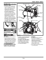
underneath tank (See Figure 4).

3. Turn power OFF and clean dust and

dirt from motor, tank, and air lines.

IMPORTANT:

Unit should be located

as far from spraying area as hose will
allow to prevent over-spray from
clogging intake port.

Operation

Do not

attach air

chuck or other tool to open end of
hose until start-up has been completed
and unit checks OK.

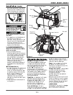
ASME SAFETY VALVE

Do not 

remove

or attempt to adjust the safety valve!

This valve should be
checked under
pressure occasionally
by pulling the ring by
hand. If air leaks after
ring has been
released, or valve is stuck and cannot
be actuated by ring, it MUST be
replaced.

REGULATOR KNOB

1. This knob controls air pressure to an

air operated tool, or paint spray gun.

2. Turning knob clockwise increases air

pressure at outlet.

3. Turning counterclockwise will lower

air pressure at outlet.

4. Fully counterclockwise will shut off

flow of air completely.

OUTLET PRESSURE GAUGE

1. This gauge shows at-a-glance, air

pressure at outlet. Air pressure is
measured in pounds per square inch
(psi).

2. Be sure this gauge reads ZERO

before changing air tools or
disconnecting hose from outlet.

TANK PRESSURE GAUGE

Gauge shows pressure in tank
indicating compressor is building
pressure properly.

4

Figure 4

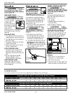
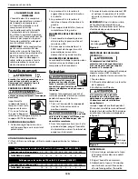
THERMAL OVERLOAD PROTECTOR

This

compressor is equipped with an manual
reset thermal overload protector which
will shut off motor if it becomes
overheated.

If thermal overload protector shuts
motor OFF frequently look for the
following causes:

1. Low voltage

2. Clogged intake port (located on

pump crankcase)

3. Lack of proper ventilation

If the

thermal

overload protector is actuated, the motor
must be allowed to cool down for 30
minutes before manually resetting.

After the unit has cooled down for 30
minutes, manually reset the thermal
overload protector by pushing the
button shown in Figure 5.

STORAGE

1. When not in use, store hose and

compressor in a cool, dry place.

2. Drain tank of moisture

3. Disconnect hose and hang open ends

down to allow any moisture to drain. 

Drain
Valve

Oilless Compressors

Figure 3

Figure 5

Thermal
overload
protector

EXTENSION CORD USE

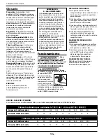
If an extension cord has to be used, use the appropriate cord based on the charts below.

www.maxustools.com

Extension cords for 120V / 3 to 4 Amp Units (EX1001, EX2001)

Length of Cord in Feet 

25 50 100 

150

200

250

300

400

500

AWG Size of Cord 

18 18 16

14

12

12

10

10

8

Extension cords for 120V / 6 to 8 Amp Units (EX8017)

Length of Cord in Feet 

25 50 100 

150

200

250

300

400

500

AWG Size of Cord 

18 

16

12

10

10

8

6

6

6

Summary of Contents for EX1001

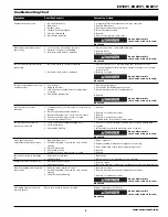
Page 1: ...he State of California to cause cancer and birth defects or other reproductive harm Wash hands after handling Please read and save these instructions Read carefully before attempting to assemble insta...

Page 2: ...sitors away and NEVER allow children in the work area 5 Wear safety glasses and use hearing protection when operating the pump or unit 6 Do not stand on or use the pump or unit as a handhold 7 Before...

Page 3: ...fer from area to area Source wiring plug and protector must be rated for at least the amperage and voltage indicated on motor nameplate and meet all electrical codes for this minimum 2 Use a slow blow...

Page 4: ...ut off flow of air completely OUTLET PRESSURE GAUGE 1 This gauge shows at a glance air pressure at outlet Air pressure is measured in pounds per square inch psi 2 Be sure this gauge reads ZERO before...

Page 5: ...lve with air in tank bleed tank 1 Check for proper fuse use time delay fuse Disconnect other electrical appliances from circuit or operate compressor on its own branch circuit 2 Replace or repair Do n...

Page 6: ...limited warranty The Purchaser must comply with the warranty given by the engine manufacturer which is supplied with the product H Additional items not covered under this warranty 1 All Compressors a...

Page 7: ...vant de mettre ce produit en service En cas de dommage ou de parties manquantes S V P composer le 1 888 MAXUS4U pour demander conseil ou appeler un Centre De Service Autoris Maxus S il vous pla t lire...

Page 8: ...t son utilisation 2 Suivre tous les codes de s curit locaux ainsi que les National Electrical Codes NEC and Occupational Safety and Health Act OSHA des U 3 Seules les personnes bien familiaris es avec...

Page 9: ...a pression du r servoir arrive la pression maximale r gl e d avance Dans la position OFF le compresseur ne fonctionnera pas Cet interrupteur devrait tre dans la position OFF pendant le branchement ou...

Page 10: ...nne obstru par la surpulv risation PROTECTEUR DE SURCHARGE THERMIQUE Ce compresseur est dot d un protecteur de surcharge thermique r armement manuel qui coupera le moteur s il surchauffe Si le protect...

Page 11: ...idanger le r servoir 1 V rifier le type de fusible utiliser un fusible retardement D brancher les autres appareils lectriques du circuit ou faire fonctionner le compresseur sur un circuit unique 2 Rem...

Page 12: ...ricant de moteur qui est fournie avec le produit H Articles suppl mentaires qui ne sont pas couverts sous cette garantie 1 Tous les Compresseurs a Toutes pi ces d tach es endommag es pendant l exp dit...

Page 13: ...edidas de Seguridad Este manual contiene informaci n que es muy importante que sepa y comprenda Esta informaci n se la suministramos como medida de SEGURIDAD y para EVITAR PROBLEMAS CON EL EQUIPO Debe...

Page 14: ...el equipo 2 Siga todos los c digos de seguridad laboral y electricidad establecidos en su pa s por ejemplo los de la NEC y OSHA en EUA 3 Este compresor s lo debe ser usado por personas que est n bien...

Page 15: ...erna del aislante es verde con o sin rayas amarillas es el cable de conexi n a tierra Nunca conecte los cables verdes o verde con rayas amarillas a un terminal con tensi n 3 Cons ltele a un electricis...

Page 16: ...Esta perilla controla el aire comprimido que se le suministra a las herramientas neum ticas o pistolas pulverizadoras 2 Gire la perilla en el mismo sentido de las agujas del reloj para aumentar la pr...

Page 17: ...be colocarse lo m s lejos posible del rea de trabajo seg n lo permita la longitud de la manguera para evitar que el filtro se atasque PROTECTOR TERMICO Este compresor est equipado con un protector de...

Page 18: ...e 1 Cerci rese de que est usando el fusible adecuado use un fusible de acci n retardada Desconecte los otros artefactos el ctricos del circuito o conecte el compresor a otro circuito 2 Reempl cela o r...

Page 19: ...clu dos de la cobertura de esta garant a limitada stos deben ser enviados por el comprador al fabricante original o a los centros de servicio autorizados por el fabricante para que se les den servicio...

Page 20: ...EX1001 EX2001 EX8017 20 Oilless Compressors Compresseur Sans Huile Compresores Sin Aceite Notes Notas...

Reviews: