2
3.3
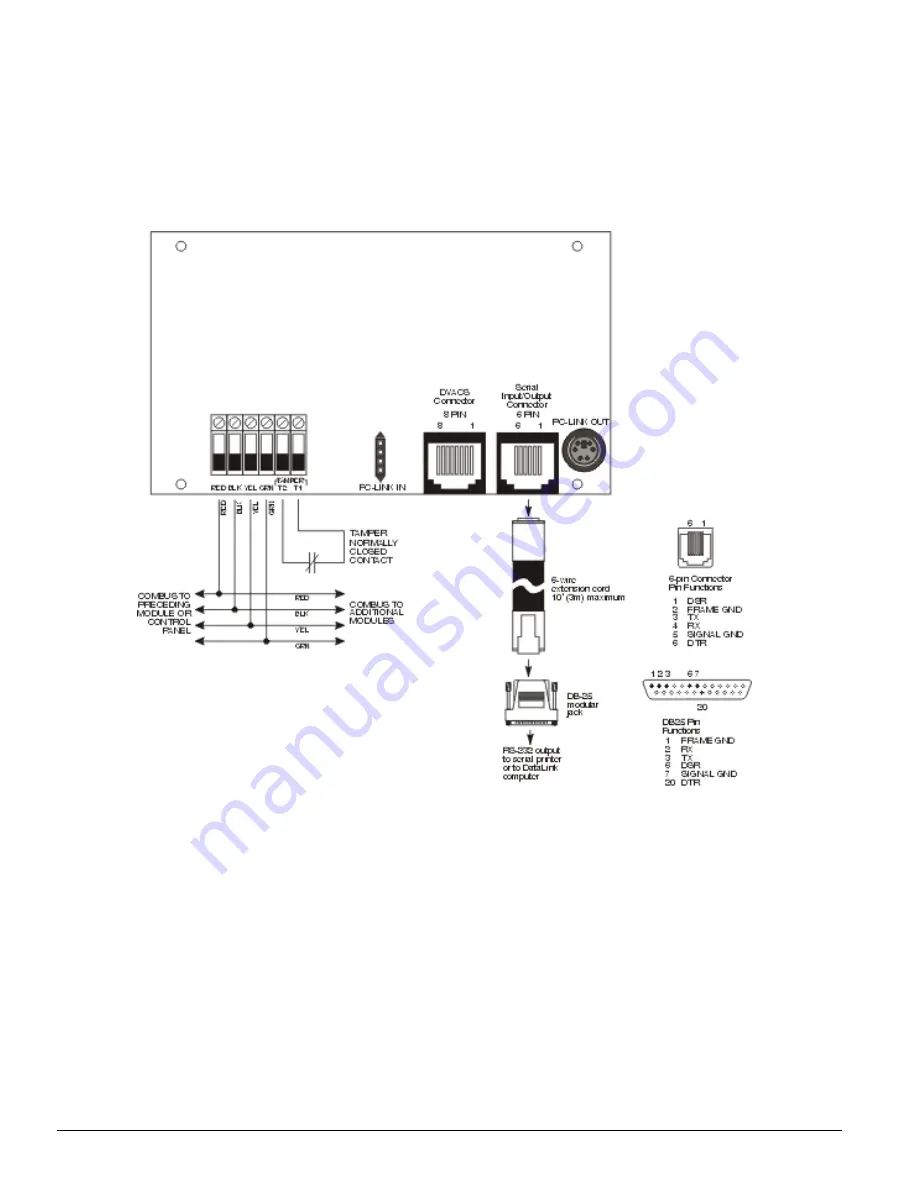
Wiring the PC4401 as a Printer or DataLink
Module*
Before beginning to wire the unit, ensure that all power
(AC transformer and battery) is disconnected from the
control panel.
Perform the following steps to complete wiring:
1. Connect the four Combus wires to the PC4401. Con-
nect the red, black, yellow and green Combus wires
to the RED, BLK, YEL and GRN terminals, respec-
tively.
2. Connect terminals T1 and T2 to a normally closed
tamper switch. If no tamper switch is desired, con-
nect a jumper wire between T1 and T2 terminals.
3. Consult Diagram 1, below for more information.
*NOTE: DataLink is not a UL nor ULC Listed feature.
Diagram 1: Connecting the PC4401 as a Printer or DataLink Module


