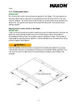
Operation of the GPC X1-LD and GPC X1-LDF liftgates
19
Operation of the GPC X1-LD and GPC X1-LDF liftgates
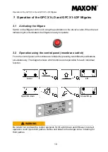
3.1 Activating the liftgate
Switch on the liftgate control unit using the pushbutton in the driver’s cabin. When the red
indicator light is illuminated, the liftgate is ready to operate.
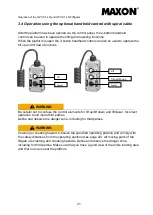
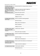
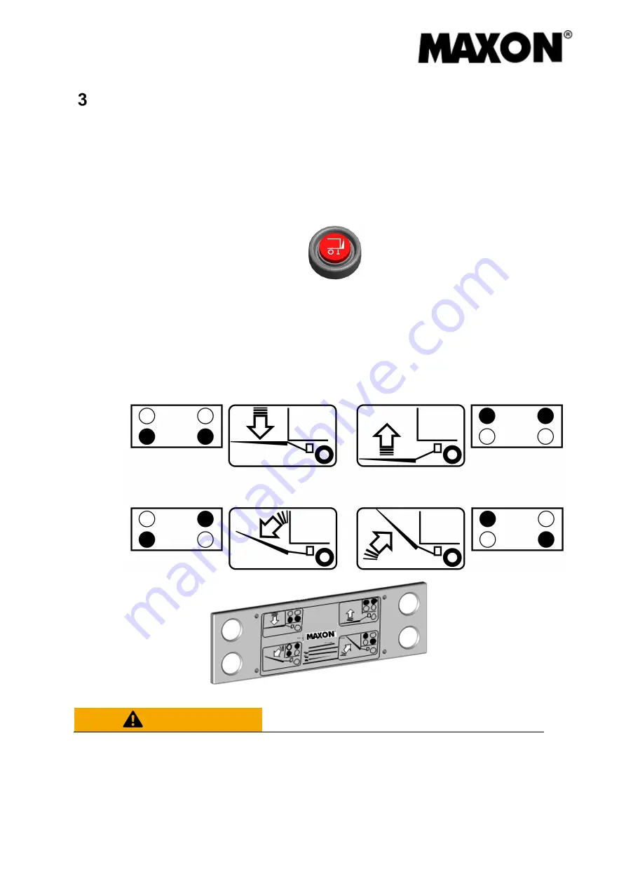
3.2 Operation using the control panel (membrane switch)
From the control panel, all functions are initiated by pressing two different pushbuttons
simultaneously. The diagram shows which buttons are responsible for each individual
function.
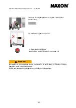
WARNING
Be careful not confuse the control elements for tilt up/tilt down and lift/lower. Incorrect
operation could injure third parties. Define and observe the danger zone, including for
third parties.
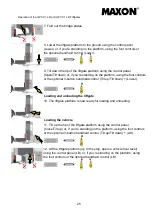
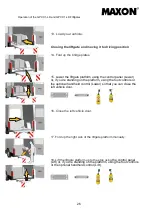
Lower
Lift
Close/tilt up
Open/tilt down
Summary of Contents for GPC X1-LD
Page 44: ...Electrical circuit diagram 40 Electrical circuit diagram...
Page 45: ...Hydraulic circuit diagram 41 Hydraulic circuit diagram...
Page 48: ...Notes 44 Notes...
Page 49: ...45...
Page 50: ...46...


