Connections
Connectors
© 2017 maxon motor. Subject to change without prior notice.
maxon motor control
EPOS2 Positioning Controller
Document ID: rel7748
4-29
EPOS2 24/2 Hardware Reference
Edition: November 2017
4.2.3
Motor/Encoder Connector (J3)
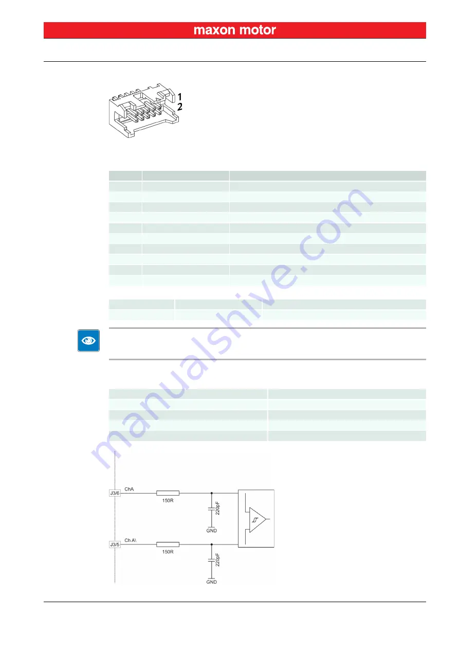
Figure 4-26
Motor/Encoder Connector (J3)
Best Practice
The use of encoder with built-in line driver is mandatory.
Even though 2-channel will do, we strongly recommend to use only 3-channel versions!
By default, the controller is set for a 500 count per turn encoder. For other encoders, you will need to
adjust respective settings via software.
Figure 4-27
Encoder Input Circuit Channel A (analogously valid also for Channel B/Index)
Pin
Signal
Description
1
Motor+
Motor terminal “+” DC version (390438) only
2
+5 VDC / 100 mA
Encoder supply voltage
3
GND
Ground
4
Motor−
Motor terminal “−” DC version (390438) only
5
Channel A\
Channel A complement
6
Channel A
Channel A
7
Channel B\
Channel B complement
8
Channel B
Channel B
9
Channel I\
Index complement
10
Channel I
Index
Accessories
Cable
Encoder Cable (275934)
Notes
Suitable connector
DIN 41651 Plug, pitch 2.54 mm, 10 poles, strain relief
Encoder supply voltage
+5 VDC
Max. encoder supply current
100 mA
Min. differential Input voltage
± 200 mV
Line receiver (internal)
EIA RS422 Standard
Max. encoder input frequency
5 MHz


