


maxon motor
Operating Instructions
4-Q-EC Servoamplifier DES 70/10
4 Operating
Instructions
4.1 Power supply layout
Any available power supply can be used, provided it meets the minimal re-
quirements set out below.
During set up and adjustment phases, we recommend separating the motor
mechanically from the machine to prevent damage due to uncontrolled motion.
Power supply requirements
Output voltage
V
CC
min. 24 VDC;
V
CC
max. 70 VDC
Ripple
< 5 %
Output current
depending on load,
continuous max. 10 A
acceleration, short-time max. 30 A
The required voltage can be calculated as follows:
Known values
Ö
Operating torque M
B
[mNm]
Ö
Operating speed n
B
[rpm]
Ö
Nominal motor voltage U
N
[V]
Ö
Motor no-load speed at U
N
, n
0
[rpm]
Ö
Speed/torque gradient of the motor
∆
n/
∆
M [rpm / mNm]
Sought value
Ö
Supply voltage
V
CC
[V]
Solution
]
[
2
9
.
0
1
)
(
0
V
M
M
n
n
n
U
V
B
B
N
CC
+
⋅
⋅
∆
∆
+
⋅
=
Choose a power supply capable of supplying this calculated voltage under load.
The formula takes a max. PWM cycle of 90 % and a 2 volts max. voltage drop
at DES 70/10 into account.
Consider:
The power supply must be able to buffer the back-fed energy from brake opera-
tion e. g. in a condenser. With electronically stabilized power supply units, care
must be taken to ensure that the overcurrent protection responds in non-
operating condition.
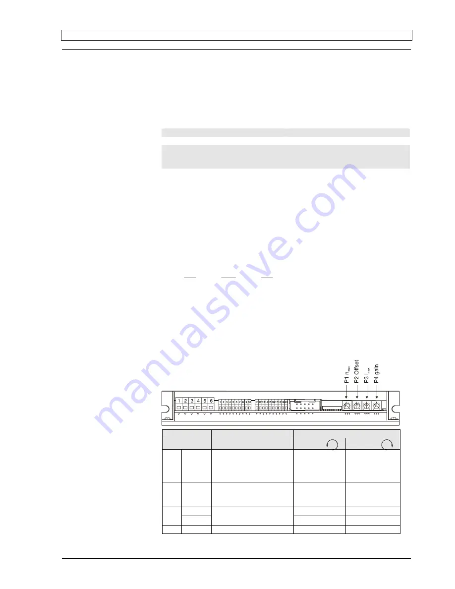
4.2 Function of the potentiometers
Potentiometer
Function
Turn to the
left
right
P1
n
max
max. speed at
max. set value (e.g.
external potentiometer
fully clockwise; 5 V; 10 V)
slower
min. 0 rpm
faster
max.
25 000 rpm
P2
Offset
Adjustment: n = 0 rpm
(set value e. g. ext. po-
tentiom. in centre pos.)
motor turns
CCW
motor turns CW
I
max
lower
≈
0A
higher
≈
30A
P3
I
cont
current limit
lower
≈
0A
higher
≈
10A
P4
gain amplification
lower
higher
April 2006 Edition / Subject to change
maxon motor control
5


