Figure 1
Figure 2
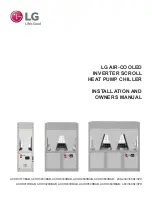
bolts, nuts and lock washers. The left brace bolts between the belt guard bracket and the transmission.
The braces are mounted to the handle bars using one 1/4” - 20 x 1 1/2 and one 1/4” - 20 x 1 3/4” hex bolts,
nuts, and lock washers. The clutch cable guide mounts on the outside of the right handle bar. Route the
clutch cable through guide with the adjustment at the top. See Figure 1.
6. Install the handle bar cross brace between the handle bars using four 1/4” - 20 x 1 1/2” hex bolts, nuts,
and lock washers. See Figure 1.
7. Route the throttle control cable under the handle passing under the cross brace.
8. Tighten all bolts at this time.
9. Install clutch cable by hooking loop at bottom into notch in clutch arm. Hook spring into clevis and into
hole in clutch lever. The clutch cable should be adjusted so that the belt will slip when released and the
spring will be extended 1/4” when lever is engaged.
10. Install handle bar grips (Some type of lubricant such as liquid soap will be helpful).
FINAL SETUP
1. Check the transmission to that it is full. See Figure 3.
a. Remove check plug.
b. Use 90 wt. gear lube or 50 weight motor oil.
Approximately 1 pint.
c. Fill until
check
plug overflows.
d. Replace plug.
2. Remove the engine dipstick and fill crankcase with oil ac-
cording to engine owner’s manual.
3. Fill fuel tank. Use clean, fresh, lead-free, gasoline. Fill
the tank completely.
DO NOT MIX OIL WITH GASOLINE.
right as you stand in an operating position. See Figure 1 and 2.
5. Install the two handle bar tie braces between the holes in the transmission and the lower holes in the
handle bars. Fasten the braces to the transmission using one 5/16” - 18 x 1” and one 5/16” x 1 1/4” hex
MT and TP Models
RMT
Ref#
Part #
Quan.
Description
Part #
Quan
Description
101
336682
1
Main Frame Rail LH
102
336681
1
Main Frame Rail RH
103
359335
2
Frame Spacer
302
130695
1
Handle Bar LH
162081
1
Handle Bar Left Hand
303
336678
2
Handle Bar Brace
304
130730
1
Handle Cross Brace
305
313786
2
Handle Grip
4
308
130694
1
Handle Bar Right Hand
162082
1
Handle Bar RH Heavy Duty
402
162077
1
Intek Throttle Control
403
402014
2
#10 - 3/8” Slot Tapping Screw
404
336683
1
Clutch Lever
405
359345
1
Clutch Lever Pin
407
359346
1
Clutch Locking Pin
408
359359
1
Clutch Locking Spring
409
359327
1
Clutch Cable Spring
410
162041
1
Clutch Cable and Adjustment
413
359326
2
Clutch Cable Guide
414
359323
1
Throttle Cable Clip
601
162031
2
Wheel, 10” x 1.75
162065
2
Wheel, 10” x 1.75” Heavy Duty
605
461467
1
Wheel Yoke Locking Pin
606
359362
1
Lock Pin Spring
607
461468
1
Cotter Pin
609
162032
1
Wheel Yoke Assembly
162033
1
Wheel Yoke Assembly
615
130701
2
Hitch Casting
618
336686
1
Depth Bar
621
359363
1
Depth Bar Adjust. Spring
625
461469
1
Depth Bar Adjust. Pin
705
359321
1
Idler Pulley
338009
1
Idler Pulley
706
162069
1
Idler Shaft
708
359325
1
Idler Shaft Arm
709
400290
1
Capscrew NC, 3/8” x 1 3/4”
802
359330
2
Wheel Shoulder Bolt
804
400184
2
Cap Screw, NC 5/16” x 3/4”
805
400186
1
Cap Screw, NC 5/16” x 1”
400190
Cap Screw, NC 5/16” x 1 1/4”
806
400197
1
Cap Screw, NC 5/16” x 2 1/4”
807
400200
4
Cap Screw, NC 5/16” x 2 1/2”
809
400207
2
Cap Screw, NC 5/16” x 3 3/4”
811
400275
1
Cap Screw, NC 3/8” x 3”
813
400115
5
Cap Screw, NC 1/4” x 1 1/2”
814
400109
1
Cap Screw, NC 1/4” x 1 3/4”
816
443101
6
Nut, NC 1/4”
817
443106
11
Nut, 5/16”
818
443110
2
Nut NC, 3/8”
819
444721
4
Locknut NC, 3/8”
820
444720
1
Locknut NF, 3/8”
821
446130
6
Lockwasher, 1/4”
822
446136
11
Lockwasher, 5/16”
825
455050
1
Washer SAE Flat, 1/2”
830
162096
Optional
LH Tine Shield
831
162095
Optional
RH Tine Shield
833
359853
1
Engine Guard
4
SET UP INSTRUCTIONS CONTINUED
13
Summary of Contents for RMT55H
Page 6: ......