Maxi MWHE20 Instruction Manual Download Page 70

20 lb.

30 lb.

40 lb.

60 lb.

80 lb.

1

A1-ST00-002

A1-ST00-002

A1-ST00-002

A1-ST00-002

A1-ST00-002

1 Set

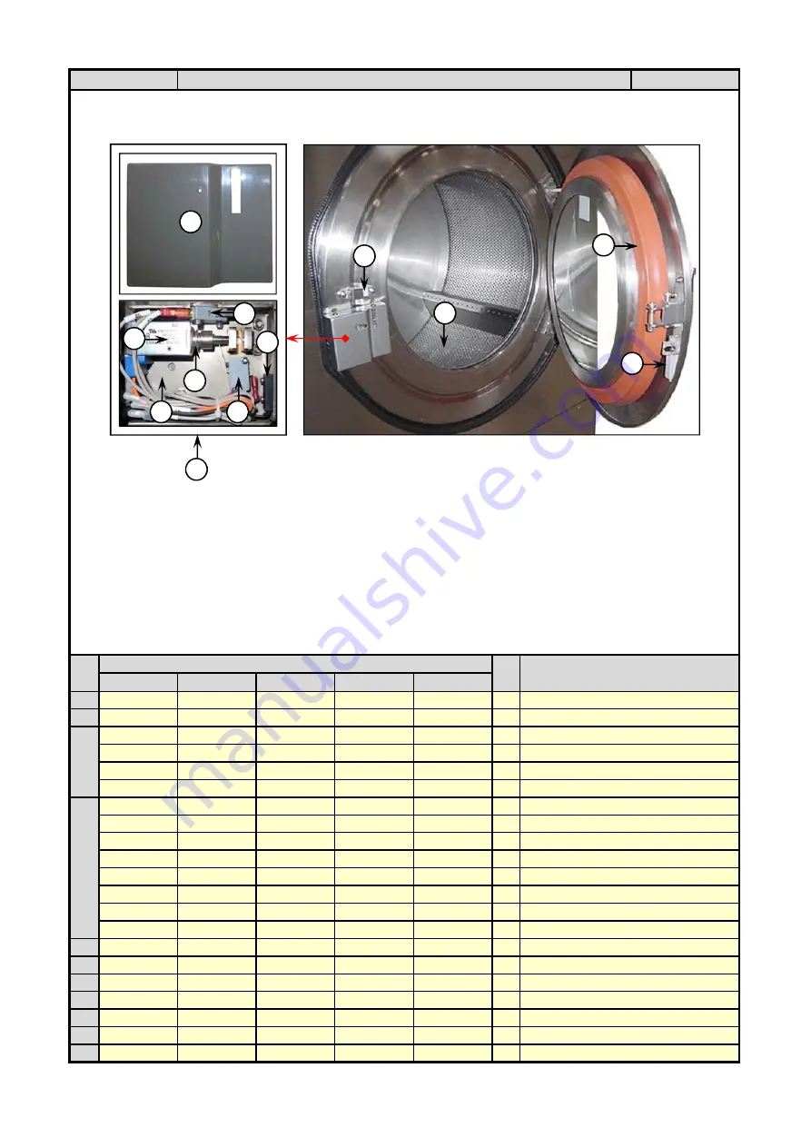
Door lock assembly complete set

2

A0-A237-001

A0-A237-001

A0-A237-001

A0-A237-001

A0-A237-001

1

 Door lock cover Plastic

A0-A001-079

-

-

-

-

1

Gasket Door, Silicone L=990mm.

A0-A001-011

A0-A001-011

-

-

1

Door Gasket Silicone Orange,  Length 44.1" 

-

-

-

A0-A001-012

-

1

Door Gasket Silicone Orange, Length 54"

-

-

-

-

A0-A001-014

1

Door Gasket Silicone Orange, Length 60.6"

A1-S204-010

-

-

-

-

1

Basket stainless steel

-

A1-S302-018

-

-

-

1

Basket stainless steel

-

-

A1-S402-018

-

-

1

Basket stainless steel

-

-

-

A1-S602-018

-

1

Basket stainless steel

-

-

-

-

A1-S802-018

1

Basket stainless steel

A0-A005-104

A0-A005-104

-

-

-

1

Seal, V-Ring  (STD)

-

-

A0-A005-105

A0-A005-105

-

1

Seal, V-Ring  (STD)

-

-

A0-A005-337

-

-

1

Seal, V-Ring (Option)

5

A0-A013-009

A0-A013-009

A0-A013-009

A0-A013-009

A0-A013-009

1

Door lock block

6

A0-A036-001

A0-A036-001

A0-A036-001

A0-A036-001

A0-A036-001

1

Magnet actuator for magnetic reed Switch (White)

7

A0-A008-120

A0-A008-120

A0-A008-120

A0-A008-120

A0-A008-120

1

Spring, Solenoid lock

8

A0-E015-018

A0-E015-018

A0-E015-018

A0-E015-018

A0-E015-018

1

Solenoid Door Lock Magnetic , Latching 1 Coil 24VDC. + Pin

9

A0-E014-015

A0-E014-015

A0-E014-015

A0-E014-015

A0-E014-015

2

Micro switch

10

A0-E014-007

A0-E014-007

A0-E014-007

A0-E014-007

A0-E014-007

1

Switch, Magnet reed

11

A1-ST00-002-01

A1-ST00-002-01

A1-ST00-002-01

A1-ST00-002-01

A1-ST00-002-01

1

Base box with Guides

Qty.

Description

Section 8

4

Part List : Door Lock Assembly

Page 6

3

Item

Part No.

1

2

3

4

5

6

7

8

9

9

10

11

Summary of Contents for MWHE20

Page 1: ......

Page 2: ...SPECIFICATIONS 2 2 SECTION 3 INSTALLATION PROCEDURES 3 1 3 1 DIMENSION CLEARANCES 3 1 3 2 MACHINE FOUNDATION 3 2 3 3 MOUNTING BOLT INSTALLATION 3 3 3 4 DRAIN CONNECTION 3 5 3 5 ELECTRICAL INSTALLATION 3 6 3 6 WATER CONNECTION 3 8 3 7 STEAM CONNECTION 3 9 3 8 EXTERNAL CHEMICAL SUPPLIES 3 9 3 9 CONTROL FUNCTION TEST 3 11 SECTION 4 OPERATING INSTRUCTIONS 4 1 SECTION 5 MAINTENANCE 5 1 5 1 DAILY 5 1 5 ...

Page 3: ...Stainless steel and steam lines can become extremely got and should not be touched Before servicing any equipment make certain it is disconnected from the electrical power source Never allow operation of the machine when any safety device is malfunctioning Never bypass safety devices This warning symbol alerts you to the presence of possible dangerous drive mechanisms within the machine Guards sho...

Page 4: ...lectrical and plumbing connections have been made in accordance with applicable codes and regulations B Make sure the machine is grounded electrically C Make sure the machine has flexible water fill and drain connections of the correct size length and type with no kinks and that they are securely attached and or clamped Before machine is placed in operation the door safety interlock must be checke...

Page 5: ...chine is not connected to a properly grounded circuit Do not bypass any safety devices in the machine Never operate the machine with a bypassed or disconnected out of balance switch Operating the machine with severe out of balance loads could result in personal injury and serious equipment damage Do not place volatile or flammable fluids in any machine Do not clean the machine with volatile or fla...

Page 6: ...the EMI regulations 5 Elevation If the machine is to be operated at elevations over 3280 feet 100 meter above sea level pay special attention to water levels and electronic settings particularly temperature or desired result may not be achieved 6 Chemicals Keep stainless steel surfaces free of chemical residues to avoid corrosion 7 Water damage Do not spray the machine with water Short circuiting ...

Page 7: ...e time from the highest attainable level If drain troughs are used they should be covered to support light foot traffic 5 Power For personal safety and for proper operation the machine must be grounded in accordance with state and local codes The ground connection must be to a proven earth ground not to conduits or water popes An easy access disconnect switch should be provided Ensure that a groun...

Page 8: ...supported by two spherical roller bearings located in a bearing housing made of cast iron The motor is controlled by the computer control located in the front and the AC inverter drive located in the rear panel Any speed can be programmed for any wash cycle Some speed ranges are blocked out for programming due to safety reasons These speed ranges are ones that the machine cannot operate at due to ...

Page 9: ... rotates A stainless steel door is provided for loading and unloading A door lock system prevents operation of the machine when the door is open The door is locked during operation utilizing an air cylinder and a manual latch for safety reasons The door lock is provided with magnetic sensor to indicate that the machine is locked and provide for start of the machine when the door is closed and lock...

Page 10: ...the crate and protective cover as soon after delivery as possible If any damages discovered upon removal of the crate and or protective cover advise the carrier and file a written claim immediately A record of each machine is on file with the manufacturer The serial number decal is located at the rear of the machine Always provide the machine s serial number and model number when ordering part or ...

Page 11: ... 3 3 7 5 5 5 7 5 7 5 10 CYLINDER SPEEDS PROGRAMMABLE Wash RPM G Force 48 5 0 8 48 5 0 8 44 4 0 8 43 0 8 39 5 0 8 39 5 0 8 Distribution RPM G Force 76 5 2 77 2 70 2 2 67 2 62 2 62 2 Extract RPM G Force 484 80 664 150 608 150 583 150 540 150 540 150 WATER INLETS AND CONSUMPTION Hot water size NPT 3 4 3 4 3 4 3 4 3 4 1 Cold water size 3 4 3 4 3 4 3 4 3 4 1 Additional water Inlet 3 4 3 4 3 4 3 4 3 4 1...

Page 12: ...SPECIFICATION COMPONENT IDENTIFICATION 2 3 C B ...

Page 13: ...models NOTE The dimensions are approximate and subject to normal manufacturing tolerances If exact dimensions are required for construction purposes request certified drawings from the factory We reserve the right to make changes at any time without notice Table 3 1 Minimum service clearances Detail Unit HARDMOUNT Series Metric US Recommended Minimum A Minimum rear clearance mm inch 760 30 305 12 ...

Page 14: ...t extra cost elevated base frames designed to handle the extreme forces encountered during the extract phase of the cycle Using other non factory designs can cause undesirable operation machine damage and in extreme circumstances injury or death Damage caused by use of non factory base frames is not covered under warranty Do not attempt to install this machine on wooden flooring of any kind above ...

Page 15: ...rs carefully allowing the machine to settle into the wet grout 5 Place the Large hardened flat washer over the Archer bolt Erasure there is no grout in and around the Archer bolt in the hole If there is clean it out so Lange flat washer makes contact with the machine base plate upper surface 6 Attached the mounting bolt washers and lock nuts to the anchor bolts after the grout has hardened Tighten...

Page 16: ...h concrete when the machine placed in position D Prepare bolting down 2 Large Hardened Flat Washer for placing over bolting down hold Model 20 60 lbs uses 5 8 11 8 M14 bolts Model 80 uses 5 8 11 8 M14 bolts Embed the bolts in 3500 psi reinforced concrete with a minimum of 12 thickness The threaded end of the bolt should extend 2 inches from the surface of the floor As an option a welded bolt locat...

Page 17: ... to prevent an airlock or siphon effect If proper drain size is not available or practical a surge tank is required A surge tank in conjunction with a sump pump should be used when gravity drainage is not possible such as in below ground level installations Before any deviation from specified installation procedures is attempted the customer or installer should contact the manufacturer Increasing ...

Page 18: ...presentative can lower the voltage or install a step down transformer kit available from the manufacturer Voltages above 250V and 490V require additional measures Contact the distributor or the manufacturer for assistance This machine must be installed adjusted and serviced by qualified electrical maintenance personnel familiar with the construction and operation of this type of machinery They mus...

Page 19: ...0 3 9 0 42 3 14AWG 2 5sq mm 6AWG 16sq mm 15 60 380 415 3 4 7 22 9 14AWG 2 5sq mm 10AWG 6sq mm 15 40 440 480 3 4 7 20 4 14AWG 2 5sq mm 10AWG 6sq mm 15 30 200 240 1 11 0 12AWG 4sq mm 20 60 lbs 200 240 3 12 0 62 0 12AWG 4sq mm 4AWG 25sq mm 20 80 380 415 3 6 5 33 9 14AWG 2 5sq mm 8AWG 10sq mm 15 50 440 480 3 6 5 30 1 14AWG 2 5sq mm 8AWG 10sq mm 15 50 200 240 1 11 0 12AWG 4sq mm 20 80 lbs 200 240 3 26 ...

Page 20: ...m of 160 F 70 C If lower temperature water is used the machine should be equipped for steam heating to heat the wash solution to desired temperature Best performance will be realized if water is provided at a pressure of 30 87 psi 2 6 Bar Although the machine will function properly at lower pressures increased fill times will occur Flush the water system for at least two minutes prior or initial u...

Page 21: ... 75 34 4 75 9 56 3 124 2 3 8 EXTERNAL CHEMICAL SUPPLIES The following procedures must be observed when connecting any chemical injector to the washer extractor See figure 3 8 Undiluted chemicals dripping can damage the machine Therefore all chemical supply dispenser pumps should be mounted below the washers injection point All dispensers tubing should also run below the injection point Loops do no...

Page 22: ...ded connectors See figure 3 9 1 Remove plugs from base 2 Install the supplied chemical nipple using Teflon tape 3 Insert tubes onto the nipples using small hose clamps or wire ties to prevent the hose from slipping off For the plastic supply box you must drill the nipples prior to use max 1 4 bit A 1 2 NPT connection is also provided for flushing systems Fig 3 9 Plastic Vacuum Breakers Supply Box ...

Page 23: ...cy button 6 Check the door interlock before starting the machine a Attempt to start the machine with the door open The machine should not start with the door open b Close the door without locking it and attempt to start the machine The washer should not start with the door unlocked c Close and lock the door and start a cycle Attempt to open the door while the cycle is in progress The door should n...

Page 24: ...pad with an LED Light Emitting Diode display This interface is located on the front of the machine In Run mode the keys function as follows Used to stop cycle in progress Used to start a cycle Used in cycle selection Pressing this key increment the cycle up by one Used in cycle selection Pressing this key decrement the cycle down by one Fig 4 1 Keypad main controller CYCLE SELECTION Press the up o...

Page 25: ...ply 3 4 FlL 6 Sixth Rinse 8th of 8 segments StoP Stop Routine Sr ln Spray Rinse SdLy Spin coast down delay Dr ln Dilution Rinse donE Cycle complete open the door PrEu Normal Prewash selected door Door not closed and locked SP ln lnE Reads spin for one second then time followed by the spin time FlLL StoP Programmed water level not reached after 30 minutes tSFL Temperature sensor failure or temperat...

Page 26: ...es not reach the desired temperature after 30 minutes the machine will progress to the next step SELECTION ADVANCE Advance Mode While any cycle is running operator can end the current step and advance to the next one by pressing the up and down key together This mode use for skip currently to next step in segment NOTE During fill water drain step of each segment the advance function can not execut...

Page 27: ...e the display shows donE the door can be opened Once the door is opened the display reverts to the cycle number of the cycle just completed The machine is now ready to run another wash program WARNING Never insert any part of your body or any object into the wash cylinder until it has completely stopped Doing so could result in serious injury NOTE If the display shows donE and the wash cylinder co...

Page 28: ... values like time and temperature when creating wash formulae The wash control WC01 Version b263 control is a four push button keys with an LED Light Emitting Diode display This interface is located on the front of the machine NORMAL DISPLAY After power ON the machine The display will show as the picture below Fig 4 2 Nomal Display The controller shows CY01 That means now the program No 1 If you n...

Page 29: ...ig 4 4 Set Mode Display Then the controller can program Prewash Wash Fill Rinse and Spin After Programming finish Press Key UP and DOWN at the same time for out of Setup mode to operate mode In the operate mode you can fine program for checking the machine Fig 4 5 Operate Mode Display STEP AFTER SETUP PROGRAM 1 1 The controller monitor will show CY 01 when finished the program setting then the con...

Page 30: ...lects degrees Fahrenheit The UP and DOWN keys toggle between the two settings The Start key accepts the selection and moves you to the next setup option Spray Rinse Supply 4 and Auxiliary Heading This setup option allows you to select among the following options Spray Rinse and Supply 4 enabled Auxiliary heat and Spray Rinse enables Auxiliary heat and Supply 4 enables To enable Spray Rinse and Sup...

Page 31: ...press the Up key while the wash cylinder temperature is displayed The display will change to show cY01 Press the up or down key until the cycle number you wish to change create is displayed Now press the Start key to begin editing your cycle Please note that the test cycle cannot be displayed or altered All programmed cycles follow a certain routine consisting of eight program segments displayed i...

Page 32: ...e the Up and Down keys to select the fill temperature The following table shows the available options Fill Temperature Options Display Fill Type hFIL Hot Fill cFIL Cold Fill bFIL Warm Fill After you have selected the appropriate fill temperature press the Start key Now you can select the Fill level by using the UP or DOWN key Select your Fill level according to the following to the following table...

Page 33: ...o skip or any time between 0 and 30 minutes HFIL cFIL bFIL Fill temperature Hot Cold or Warm both fill SUP0 SUO7 Select Supply 0 7 0 for no supply during the step 00 75 200 Enter temperature 75 200 deg F 25 93 deg C 00 for no heat Select 00 if you have programmed a Flushing Prewash 00 25 93 SPIn flases for 1 sec t IrE flases for 1 sec 00 or 30 120 Select time for spin 30 120 seconds 00 for no spin...

Page 34: ... 30 120 seconds 00 for no spin NOTE Supply 4 and 7 are only available if enabled in Setup NOTE Heat is only available if enabled in Setup NOTE If Spray Rinse is selected for the segment steps 3 to 6 are skipped Fill 6 Segment Display detiail Use Up or Down to change Start key is enter or advance FIL 6 00 or 02 30 Segment time 00 to skip or any time between 0 and 30 minutes HFIL cFIL bFIL Fill temp...

Page 35: ... 7 975 0 1011 8 SP HP HE 40 0 680 m 850 8 888 7 925 0 959 9 SP HP HE 60 0 790 m 789 4 824 5 858 2 890 6 HE 80 0 924 m 729 9 762 4 793 5 823 4 SP HP 100 0 940 m 723 7 755 8 786 7 816 4 SI 110 0 940 m 723 7 755 8 786 7 816 4 SI 135 1 092 m 671 4 701 3 729 9 757 5 SI 200 1 169 m 648 9 677 8 705 5 732 1 SI 275 1 321 m 610 5 637 6 663 6 688 7 SI 300 1 321 m 610 5 637 6 663 6 688 7 SI 450 1 629 m 549 7 ...

Page 36: ...t to start the washer with the door open The washer should not start with the door open b Close the door without locking it and attempt to start the machine The machine should not start with the door open c Close and lock the door and start a cycle Attempt to open the door while the cycle is in progress The door should not open If manual latch is moved out of position the machine should stop If th...

Page 37: ...stroke Do not pump the grease gun if grease comes out of the bearing housing This can result in over lubrication causing damage to bearings and seals 2 If the machine is provided with automatic lubricators check that they are injecting grease Normally they last for approximately one year Mark new lubricators with installation date 3 Clean the AC drive fins a Remove the AC drive box cover b Blow th...

Page 38: ...re metal matching paint is available from the manufacturer a If bare metal is showing paint with primer or solvent based paint b If rust appears remove it with sand paper or chemical means Then paint with primer or solvent based paint 4 Clean steam filter where applicable See Figure 5 3 5 Remove back panel and check overflow hose and drain hose for leaks 6 Remove top cover and check the supply dis...

Page 39: ...less steel Use stainless steel wool or soft non metal bristle brushes 5 If the stainless appears to be rusting the source of the rust may actually be an iron or steel part not made of stainless steel such as a nail or screw One remedy is to paint all carbon steel parts with a heavy protective coating Stainless steel fasteners should be used when possible 6 Discoloration or heat tint from overheati...

Page 40: ...rmally Check for abnormal noise odor or excessive vibration Check for traces of overheats discoloration and other defects Judgment of service life using maintenance information Menu 5 Maintenance information in Programming mode can be used to display data for the judgment of replacement of DC bus capacitor electrolytic capacitor on the printed circuit board and cooling fan as a guide If the replac...

Page 41: ...the inverter power on 4 Check that the cooling fan rotates and the inverter is on halt 5 Turn the main power supply off Start measuring the capacitance of the DC bus capacitor 6 After the LED monitor is unlit completely turn the main power supply on again 7 Select Menu 5 Maintenance Information in Programming mode and check the reduction ratio of the capacitance of the DC bus capacitor 2 Electroly...

Page 42: ...Disconnect hoses a Disconnect drain hose from sump Gutter or drain b Turn off water supply Disconnect individual hot and cold water inlet hoses from the machine c Disconnect the compressed air supply to the machine d Allow time for residual water in the machine to drain e Then disconnect drain hoses from the machine f Disconnect necessary plumbing on the re circulation system if applicable 5 Disco...

Page 43: ...r output terminals U V and W Some electric charge may remain in the DC bus capacitor even after the power is turned off Therefore it may take some time until the DC link circuit voltage reaches a safe level Before touching the circuit wait for at least five minutes after the power has been turned off and check that the DC voltage between main circuit terminals P and N is less than 25 VDC using a m...

Page 44: ...tion P 7 11 OH1 Overheat protection for heat sink P 7 11 OH2 External alarm input P 7 12 OH4 PTC thermistor for motor protection P 7 12 dbH Overheat protection for braking resistor P 7 13 OL1 Electronic thermal overload relay P 7 14 OLU Overload protection P 7 14 Er1 Memory error P 7 15 Er2 Remote keypad communications error P 7 15 Er3 CPU error P 7 16 Er6 Operation protection P 7 16 Er8 RS485 com...

Page 45: ...command with Menu 4 I O Checking using the keypad Input the rotation direction F02 0 or select the keypad operation with which the rotation direction is fixed F02 2 or 3 4 The inverter could not accept any run commands from the keypad since it was not in Running mode Check which operation mode the inverter is in using the keypad Shift the operation mode to Running mode 5 A run command with higher ...

Page 46: ...ect ones 9 The coast to stop command was effective Check the data of function codes E01 E02 E03 E98 and E99 with Menu 2 Data Checking and the input signal status with Menu 4 I O checking using the keypad Release the coast to stop command setting 10 Broken wire incorrect connection or poor contact with the motor Check if the output current and connection are correct Repair the wires to the motor or...

Page 47: ...a value Check the higher priority run command with Menu 2 Data checking and Menu 4 I O checking using the keypad referring to the block diagram of the drive command generator Refer to the FRENIC Mini User s Manual MEH446 Correct any incorrect function code data settings e g cancel the higher priority run command etc 5 The acceleration deceleratio n time was too long Check the data of function code...

Page 48: ...hecking using the keypad Increase the filter constants C33 and C38 for the frequency command 2 The external frequency command device was used Check that there is no noise in the control signal wires from external sources Isolate the control signal wires from the main circuit wires as far as possible Use shielded or twisted wires for the control signal 3 The slip compensation gain was too large Che...

Page 49: ... resistor Increase the deceleration time F08 and E11 4 Overload Measure the output current Lighten the load 5 Torque generated by the motor was insufficient Check that the motor starts running if the value of the torque boost F09 is increased Increase the value of the torque boost F09 6 An external frequency command device is being used Check that the there is no noise in the external signal wires...

Page 50: ...e detection level Check the DC link circuit voltage with Menu 5 Maintenance information and measure the input voltage using the keypad Supply power to match the inverter s input rating and change the data of the function codes 2 The desired menu is not displayed Possible Causes What to Check and Suggested Measures 1 The limiting menus function was not selected appropriately Check the data of funct...

Page 51: ...erefore use this information to judge if the trend is over the calculated load value for your system design If the load is too heavy decrease it or raise the inverter capacity Trace the current trend and check if there are any sudden changes in the current If there are any sudden changes make the load variation smaller or raise the inverter capacity Enable current limiting H12 4 The value set for ...

Page 52: ...rom the moment of inertia for load and the deceleration time Increase the deceleration time F08 E11 and H54 Enable automatic deceleration H69 1 so that when the DC link circuit voltage exceeds the over voltage suppression level the inverter changes the deceleration time to three times longer than the set value Set the rated voltage at base frequency F05 to 0 to improve braking ability Consider the...

Page 53: ...lfunctioned or which connection is incorrect Replace any faulty peripheral equipment or correct any incorrect connections 5 Other loads were connected to the same power system and required a large current to start running to the extent that it caused a temporary voltage drop Measure the input voltage and check the voltage variation Reconsider the power system configuration 6 Inrush current caused ...

Page 54: ... Measure the output current Replace the motor 3 The terminal screws for inverter output were not tight enough Check if any terminal screws have become loose Tighten the terminal screws to the recommended torque 4 A single phase motor has been connected Single phase motor cannot be used Note that the FRENIC Mini only drives three phase induction motors 6 OH1 Overheat protection for heat sink Proble...

Page 55: ...k if the wire for the external alarm signal is correctly connected to the terminal to which the Alarm from external equipment has been assigned Connect the wire for the alarm signal correctly 3 Incorrect settings Check if the Alarm from external equipment has been assigned to an unassigned terminal Correct the assignment 8 OH4 PTC thermistor for motor protection Problem Temperature of the motor ro...

Page 56: ...ures 1 Braking load was too heavy Recalculate the relation between the braking load and braking capacity Lighten the braking load Reconsider the braking resistor in order to improve braking ability Resetting the data of function codes F50 and F51 is also required 2 The deceleration time was too short Recalculate the required deceleration torque and time from the moment of inertia for the load and ...

Page 57: ...inadequate Check the continuous allowable current of the motor Reconsider and change the data of function code F11 11 OLU Overload protection Problem Temperature inside inverter rose abnormally Possible Causes What to Check and Suggested Measures 1 Temperature around the inverter exceeded that of inverter specifications Measure the temperature around the inverter Lower the temperature e g ventilat...

Page 58: ...enable writing of data Check if pressing the PRG RESET key resets the alarm after the function code data are initialized by setting the data of H03 to 1 Return the initialized function code data to their previous settings and then restart the operation 2 A high intensity noise was given to the inverter while data especially initializing data was being written Check if appropriate noise control mea...

Page 59: ... Suggested Measures 1 A high intensity noise was given to the inverter Check if appropriate noise control measures have been implemented e g correct grounding and routing of control and main circuit wires Improve noise control 2 The printed control circuit board in the inverter malfunctioned Replace the board 15 Er6 Operation protection Problem an error occurred due to incorrect operation of the m...

Page 60: ...ontact Check continuity of the cable contacts and connections Replace the cable 4 Even though no response error detection time y08 has been set communications did not occur cyclically Check the host controllers Change the settings of host controller software or make the no response error detection time invalid y08 0 5 A high intensity noise was given to the inverter Check if appropriate noise cont...

Page 61: ...ssing the PRG RESET key and releasing the alarm reset the data such as the frequency commands timer and PID process commands set with the keypad to the correct settings and then restart the motor 2 A high intensity noise was given to the inverter while data was being written when the power was turned off Check if appropriate noise control measures have been implemented e g correct grounding and ro...

Page 62: ...the name plate 2 Part number part name and quantity required Use this manual to facilitate ordering 3 When ordering electrical motors please include complete name plate data motor manufacturer and wiring diagram number Our service and spare parts department consists of specially trained personnel to assist you with your needs Please do not hesitate to call if we can be of any assistance to you ...

Page 63: ... CPU A1 S204 036 1 Panel Front top 3 Cup SUS A1 S302 033 1 Panel Front top 4 Cup SUS A1 S402 033 1 Panel Front top 4 Cup SUS A1 S602 047 1 Panel Front top 4 Cup SUS A1 S802 043 1 Panel Front top 4 Cup SUS A1 S204 041 1 Panel Front top 3 Cup Anthracite Grey Panels A1 A302 054 1 Panel Front top 4 Cup Anthracite Grey Panels A1 S402 053 1 Panel Front top 4 Cup Anthracite Grey Panels A1 S602 059 1 Pane...

Page 64: ...1 Right Panel Assembly SUS A1 S302 048 1 Right Panel Assembly Painted A1 S402 047 1 Right Panel Assembly Painted A1 S602 053 1 Right Panel Assembly Painted A1 S802 048 1 Right Panel Assembly Painted A1 S204 033 1 Left Panel Assembly SUS A1 S302 051 1 Left Panel Assembly SUS A1 S402 050 1 Left Panel Assembly SUS A1 S602 056 1 Left Panel Assembly SUS A1 S802 051 1 Left Panel Assembly SUS A1 S302 049...

Page 65: ...062 02 1 Lid Chemical dispenser 4 compartments Plastic 9 A0 A095 062 01 A0 A095 062 01 1 Body Chemical dispenser 4 compartments Plastic 10 A0 A030 004 A0 A030 004 A0 A030 004 Plastic cups 20lb 3 Qty 30 40lb 4 Qty 11 A0 A030 006 A0 A030 006 4 Plastic cups Plastic dispenser 12 A0 A095 002 A0 A095 002 A0 A095 002 A0 A095 002 A0 A095 002 Nozzle 20lb 3 Qty 30 40 60 80lb 4 Qty 13 A0 A029 001 A0 A029 001...

Page 66: ...Grey Panels A1 S204 040 1 Top panel assembly Top Dispenser SUS A1 S302 053 1 Top panel assembly Top Dispenser SUS A1 S402 052 1 Top panel assembly Top Dispenser SUS A1 S302 060 1 Top panel assembly Top Dispenser Anthracite Grey Panels A1 S402 061 1 Top panel assembly Top Dispenser Anthracite Grey Panels 3 A0 A095 076 A0 A095 076 A0 A095 076 1 Set Chemical Dispenser Plastic 3 Cup Page 3 Item Part N...

Page 67: ... S802 012 1 Front panel tub A1 S204 026 1 Door hinge A1 SHE2 002 A1 SHE2 002 1 Door hinge A1 S602 015 1 Door hinge A1 S802 015 1 Door hinge A0 A081 006 A0 A081 006 A0 A081 006 A0 A081 006 A0 A081 006 4 Cap nut A0 A057 003 A0 A057 003 A0 A057 003 A0 A057 003 A0 A057 003 4 Bolt studs stainless A0 A057 002 A0 A057 002 A0 A057 002 A0 A057 002 A0 A057 002 12 Bolt studs stainless A0 A081 005 A0 A081 005...

Page 68: ...ge bracket A1 S802 029 1 Door hinge bracket 10 A0 A033 002 A0 A033 002 A0 A033 002 A0 A033 002 A0 A033 002 1 Door hinge bushing 11 A0 A033 003 A0 A033 003 A0 A033 003 A0 A033 003 A0 A033 003 1 Bolt Shoulder Door hinge 12 A1 SSP2 005 A1 SSP2 005 A1 SSP2 005 A1 SSP2 005 A1 SSP2 005 1 Door hinge washer Item Part No Qty Description 9 ...

Page 69: ...A0 TSA01 496 A0 TSA01 496 A0 TSA01 496 1 Door Handle Pivot Spring 5 A0 A033 005 A0 A033 005 A0 A033 005 A0 A033 005 A0 A033 005 1 Door Latch Shoulder Bolt 6 A0 A033 004 A0 A033 004 A0 A033 004 A0 A033 004 A0 A033 004 1 Door Handle latch Bush 7 A1 ST00 001 04 A1 ST00 001 04 A1 ST00 001 04 A1 ST00 001 04 A1 ST00 001 04 1 Door Handle B body 8 A1 ST00 001 02 A1 ST00 001 02 A1 ST00 001 02 A1 ST00 001 0...

Page 70: ...l V Ring STD A0 A005 105 A0 A005 105 1 Seal V Ring STD A0 A005 337 1 Seal V Ring Option 5 A0 A013 009 A0 A013 009 A0 A013 009 A0 A013 009 A0 A013 009 1 Door lock block 6 A0 A036 001 A0 A036 001 A0 A036 001 A0 A036 001 A0 A036 001 1 Magnet actuator for magnetic reed Switch White 7 A0 A008 120 A0 A008 120 A0 A008 120 A0 A008 120 A0 A008 120 1 Spring Solenoid lock 8 A0 E015 018 A0 E015 018 A0 E015 01...

Page 71: ... 1 Reuse Drain plug A0 A001 034 A0 A001 034 1 Reuse Drain plug A0 A018 113 1 Drain Hose ID 60 mm A0 A018 072 A0 A018 072 1 Drain Hose 60MM Length 450MM A0 A018 071 1 Drain Hose 3 Length 460MM A0 A018 070 1 Drain Hose 3 Length 600MM A1 SSP2 022 A1 SSP2 022 A1 SSP2 022 A1 SSP2 022 1 Steam Injector Size 3 4 X1 2 for Steam Type A1 SSP2 037 1 Steam Injector Size 1 X1 2 for Steam Type 5 Item Part No Qty...

Page 72: ... 060 A0 E007 060 A0 E007 060 A0 E007 060 A0 E007 060 1 Ribbon Cable Connector 14 Pins 6 A0 E007 015 A0 E007 015 A0 E007 015 A0 E007 015 A0 E007 015 1 Cable Ribbon 16Pos 7 A0 E007 171 A0 E007 171 A0 E007 171 A0 E007 171 A0 E007 171 1 Cable 24 AWG 4C Size 24 inch 4 Pin 8 A0 E007 403 A0 E007 403 A0 E007 403 A0 E007 403 A0 E007 403 1 Cable Assembly Link Cable A0 A050 027 A0 A050 027 A0 A050 027 A0 A05...

Page 73: ...se Water Supply 30 60 80lb 2 Qty 40lb 3 Qty 5 A0 A018 016 A0 A018 016 A0 A018 016 A0 A018 016 A0 A018 016 Hose Water Supply 20lb 3 Qty 30 40 60 80lb 4 Qty A0 A018 113 1 Dispenser Hose A0 A018 075 1 Dispenser Hose A0 A018 074 A0 A018 074 1 Dispenser Hose A0 A018 073 1 Dispenser Hose A0 A127 001 A0 A127 001 1 Vacuum Breaker A0 A127 002 A0 A127 002 A0 A127 002 1 Vacuum Breaker Item Section 8 Part No ...

Page 74: ... A1 S204 015 1 Shell assembly ring A1 S302 023 1 Shell assembly ring A1 S402 023 1 Shell assembly ring A1 S602 023 1 Shell assembly ring A1 S802 023 1 Shell assembly ring A0 A001 003 A0 A001 003 A0 A001 003 A0 A001 003 A0 A001 003 1 Gasket front panel tub 11 A0 E047 076 A0 E047 076 A0 E047 076 A0 E047 076 A0 E047 076 1 Solenoid Steam Valve 1 2 A0 A017 045 A0 A017 045 A0 A017 045 A0 A017 045 1 Flex...

Page 75: ...ter Supply 3 4 4 A0 A018 016 A0 A018 016 A0 A018 016 3 Hose Water Supply Flush Hose 1 2 A0 A018 113 1 Drain Hose HC 20 ID 60 mm A0 A018 075 1 Dispenser Hose A0 A018 074 1 Dispenser Hose A0 A127 001 A0 A127 001 1 Vacuum Breaker Plastic A0 A127 002 1 Vacuum Breaker Plastic Section 8 Part List Water Dispenser Valve Assembly Top Dispenser Page 10 Item Part No Qty Description 3 5 6 1 2 3 4 5 Model 20 3...

Page 76: ... 006 A0 E012 006 A0 E012 006 A0 E012 006 1 Fan Cooling A0 E012 009 A0 E012 009 A0 E012 009 A0 E012 009 A0 E012 009 1 Filter for fan A0 A028 003 A0 A028 003 A0 A028 003 1 Electrical connection Main power A0 A028 003 A0 A028 003 1 Electrical connection Main power for Electric Type Electrical connection Main power for Steam Type Hot Water Type 7 A0 A028 002 A0 A028 002 1 Electrical connection Chemica...

Page 77: ...029 1 Circuit breaker 6A 5 A0 E021 039 A0 E021 039 A0 E021 039 A0 E021 039 A0 E021 039 1 Block Terminal A0 E021 031 1 A0 E021 031 1 A0 E021 031 1 A0 E021 031 1 A0 E021 031 1 1 Terminal Block 3 Pole A0 E021 031 2 A0 E021 031 2 A0 E021 031 2 A0 E021 031 2 A0 E021 031 2 1 Terminal Block 4 Pole 7 A0 E055 001 A0 E055 001 A0 E055 001 A0 E055 001 A0 E055 001 1 Connector Ground Lug A0 E004 069 A0 E004 069...

Page 78: ...ker 1A 5 A0 E021 039 A0 E021 039 1 Terminal Block 10P A0 E021 031 1 A0 E021 031 1 1 Terminal Block 3 Pole A0 E021 031 2 A0 E021 031 2 1 Terminal Block 4 Pole 7 A0 E055 001 A0 E055 001 1 Connector Ground Lug A1 ST01 005 1 Electric enclosure Rear A1 ST01 006 1 Electric enclosure Rear 1 Section 8 Page 13 4 6 8 Part List Electrical Control Unit Item Part No Qty Description 4 2 1 8 6 3 7 5 4 2 1 8 6 3 ...

Page 79: ... A0 A007 045 1 Housing A0 A007 016 1 Housing A0 A007 043 A0 A007 043 1 Housing A0 A004 067 A0 A004 067 1 Ball bearing Rear A0 A004 111 A0 A004 111 1 Ball bearing Rear A0 A106 003 A0 A106 003 1 Hose nipple A0 A106 004 A0 A106 004 1 Hose nipple A1 S204 030 1 Set Bearing Housing Complete set A1 SHE1 026 1 Set Bearing Housing Complete set A1 SHE1 027 A1 SHE1 027 1 Set Bearing Housing Complete set 4 7 ...

Page 80: ... A004 001 1 Bearing 8 A0 A006 017 1 Lock Washer 9 A0 A006 016 1 Lock Nut 10 A0 A005 101 1 Seal V Ring 11 A1 SSP2 019 1 Seal Plate Front 12 A1 SSP2 021 1 Seal Plate Flat Front 13 A0 P006 070 3 fitting 14 A0 A106 004 1 Hose Nipple 15 A0 A007 012 1 Housing 16 A1 SSP2 020 1 Seal Plate Rear 17 A1 S802 047 1 Set Bearing Housing Complete set Part No Description Section 8 Qty Part List Bearing Housing Ass...

Page 81: ...PH A0 E008 481 1 Motor 3HP 4P 190 380V 60HZ 3PH A0 E008 890 1 Motor 5 HP 4 P 190 380V 60Hz A0 E008 482 1 Motor 7 5HP 4P 190 380V 60HZ 3PH 1 Part List Main Drive Item Part No Qty Description Page 16 Section 8 2 3 4 5 7 8 9 11 14 15 6 10 1 2 3 4 5 6 7 8 9 10 11 14 15 20 lb 30 40 60 80 lb 1 16 16 Option 20 19 18 17 13 12 ...

Page 82: ...n A1 S202 041 1 Tension spring mounting plate A1 S302 041 1 Tension spring mounting plate A1 S402 041 1 Tension spring mounting plate A1 S602 041 1 Tension spring mounting plate A0 E041 004 A0 E041 004 A0 E041 004 1 Drain valve assembly A0 E041 002 A0 E041 002 1 Drain valve assembly 11 A0 A237 005 A0 A237 005 A0 A237 005 A0 A237 005 A0 A237 005 1 Set Cover Box Mounting Box Drain Valve Plastic Comp...

Reviews: