


Copyright Maxford USA 2017
Page 11 of 12
S171201
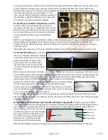
Installing the optional landing gear and tail skid set:
To fly this airplane from the land, test-fit the landing gear at approx.
5-inches in front of the step of bottom, then mark where to drill holes
for the bolts and blind nuts included with the landing gear kit.
Glue some
scrap ply-
wood (not
included)
inside the
bottom of
the fuselage
where the bolt holes will be drilled. After the glue is fully cured, drill the holes and install the blind nuts
as pictured above. Attach and reinforce the landing gear using the bolts, supplied steel cables and crimp
tubes as pictured at the right.
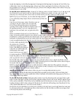
Apply threadlock compound or
CA adhesive to ensure the
wheels remain securely
attached to the landing gear
strut. Attach the tail skid to the
bottom of the the small
triangular-shaped fin at the bottom of the fuselage using glue and/or screws as pictured above.
(NOTE: to maintain optimal water-based operation, remove landing gear bolts add rubber washers,
then screw bolts back. Using a steerable tail wheel is not recommended.)
To install your radio receiver and perform final setup
, connect the aileron, elevator and
rudder servos, glow-plug wires if used, or ESC-to-motor wires if used, and your throttle servos or
ESCs to your radio receiver.
Align and slide the wing’s leading-edge pins into their corresponding holes in the fuselage, then snugly
attach (but do not over tighten) the wing-retaining screws in the blind nuts in their wing-saddle
mounting blocks. NOTE: some flying boat fans like to create an improved water seal at the wing
saddle by adding weather stripping such as M-D Building Products’ white ‘Rubber Weatherseal,’
available at hardware stores.
Setup your radio as instructed by the maker of your radio system, carefully making any necessary
adjustments to servo directions and control throws.
Setup your power system as instructed by the maker of your engines or motors.
NOTE: you may install pieces of triangular-shaped material as strakes. If you prefer to not enjoy
‘drifting’ on the water during high-speed turns, you may use epoxy to attach a strake at the center of
the fuselage immediately in front of the step and/or immediately behind the step.
Use the preinstalled rare-earth magnets to install the pod’s hatches, and add any optional (not
included) decorative markings and/or trim stickers you may desire.
CONGRATULATIONS! ASSEMBLY IS FINISHED!
IX. INITIAL SETUP, ADJUSTMENTS AND PREFLIGHT CHECKS
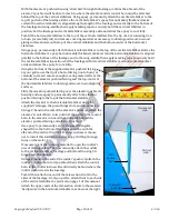
1.
The Neptune’s center of gravity (CG) must fall within 3¾-inches to 4½-inches (approx. 102 mm) back
from the leading edge of the wing. If necessary, move batteries and/or add weight to the nose or tail to
ensure the CG is correct.
2.
Check the heat-shrink covering material’s joints and surfaces; if necessary, carefully use a dedicated
covering-material iron to secure the edges and to tighten any loosened areas. Recheck and retighten
from time to time, being especially careful to keep the edges well sealed to prevent water leakage.
Approx. 5 inches
Step
N
o
s
e