


Copyright Maxford USA 2017
Page 10 of 12
S171201
With the elevator’s pushrod housing ‘stretched’ through the fuselage, confirm the aft-end of the
elevator’s pushrod will be able to reach to where the elevator and its control horn must be attached
behind the top of the vertical stabilizer. Using epoxy, permanently attach the vertical stabilizer to the
top-aft portion of the fuselage. Before the vertical stabilizer’s epoxy has noticeably thickened, make
certain the vertical stabilizer is aligned along the length of the fuselage and vertically to the bottom of
the fuselage and wing-saddle, then apply masking tape to securely hold the vertical stabilizer in
position. Set the fuselage and vertical stabilizer assembly aside and allow the epoxy to cure fully.
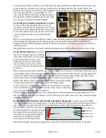
Test-fit the horizontal stabilizer to the top of the vertical stabilizer. Use the tip of a hot soldering iron
to burn (or carefully cut) and remove covering material as necessary to obtain good wood-to-wood
gluing surfaces between the top of the vertical stabilizer and the bottom-center of the horizontal
stabilizer.
Using epoxy, permanently attach the horizontal stabilizer to the top of the vertical stabilizer. Before the
horizontal stabilizer’s epoxy has noticeably thickened, make certain the horizontal stabilizer is aligned
parallel to the bottom of the fuselage and to the wing-saddle, then apply masking tape to securely hold
the vertical stabilizer in position. Set the fuselage with its vertical stabilizer and horizontal stabilizer
aside and allow the epoxy to cure fully.
Using the bottom of the supplied elevator pushrod fairing
as your guide, use the tip of a hot soldering iron to burn (or
carefully cut) and remove enough covering material from the
bottom of the elevator pushrod fairing and the top-center of
the horizontal stabilizer to obtain good wood-to-wood gluing
surfaces.
Slide the elevator pushrod fairing over the elevator pushrod’s
housing and use epoxy to permanently attach the elevator
pushrod fairing to the top of the horizontal stabilizer.
Attach the elevator to the horizontal stabilizer using the
supplied CA hinges, the precut hinge slots, and CA adhesive.
Using a Z-bend in the end of the elevator’s pushrod, attach the
elevator’s control horn to its pushrod, then attach the control
horn to the elevator in line with and directly behind the
elevator pushrod fairing and elevator pushrod.
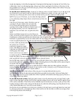
Use epoxy to permanently secure the small triangular-
shaped fin to the bottom of the fuselage in line with the
aft-end of the vertical fin. (NOTE: some customers choose
not to install this small fin to better enjoy ‘drifting’ through
turns on the water.)
If necessary, cut the covering material to open the rudder’s
precut CA hinge slots. Then permanently attach the rudder
to the vertical stabilizer, fuselage and bottom fin using CA
hinges and CA adhesive.
Using a Z-bend in the end of the rudder’s pushrod, attach the
rudder’s control horn to its pushrod, then attach the control
horn to the rudder in line with and directly behind where the
rudder pushrod exits the fuselage.
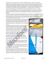
Test-fit then attach one end of the tail-section struts to the
sides of the fuselage. Or, if you prefer, attach them to each side
of the vertical stabilizer as pictured on page 1 of this manual.
Attach the upper ends of the tail-section struts to the wooden
‘hardpoints’ in the horizontal stabilizer as shown at the right.
Triangular-
shaped fin
Tail-
section
strut
Horizontal
stab.
Vertical
stab.