S110908 Mentor-G V2
43.
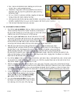
Tighten a supplied self-locking nut onto the remaining exposed threads at the inside of each axle bolt,
secure the axle bolt against vibration by applying a drop of thick CA adhesive to the exposed threads at
each self locking nut, and return the airplane to its ‘right side up.’
Congratulations! Assembly is finished!
VII. SETUP AND ADJUSTMENTS:
1.
For initial flights set the M
ENTOR
-G
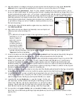
V2’s center of gravity (CG) at approx. 3 3/4-
inches back from the leading edge of the wing. If necessary, move the batteries and/or
add weight to the nose or tail to ensure the CG is correct.
(Hint: Once you have determined the final position for your CG, you may secure both
the engine’s and radio’s batteries in place with double-sided foam tape and pack
some scrap foam rubber into the fuselage’s nose-area around the batteries and fuel
tank to help secure these items against vibration.)
2.
Check the Mylar covering material’s joints and surfaces; if necessary, carefully use a
dedicated covering-material iron to secure the edges and to tighten any loosened areas.
Recheck and retighten from time to time.
3.
Check/adjust servo centering, direction and end-point adjustments. When you pull the
right stick toward you, the elevator should deflect upwards; push the right stick to the
right and the right aileron should deflect upwards and the left aileron should deflect
downwards; push the left stick left and the rudder should deflect to the left as viewed
from the rear of the fuselage. Review your radio’s instruction manual if you require
assistance with any radio-related setup and/or servo-adjustment questions.
4.
For initial flights set all linkages for near-max. possible deflections. If you are using a
Computer Radio: soften the aileron’s and elevator’s control throws by applying 30%
exponential.
Initial settings if you are using a Non-Computer Radio:
Low
rates High
rates
Ailerons ................. +10 degrees (+3/8-inch) ........... +15 degrees (+1/2-inch)
Elevator ................. +10 degrees (+3/8-inch) ........... +15 degrees (+1/2-inch)
Rudder ................... +10 degrees (+3/4-inch) ........... +15 degrees (+7/8-inch)
5.
Trim adjustments: The ailerons and rudder will probably require no adjustments (in all
probability you will be able to leave them centered, as assembled); however, be
prepared to set the elevator trim depending on how slow or fast you fly. For example, if
you like flying low and slow, your M
ENTOR
-G’s elevator may require a bit of up-trim.
VIII. PREPARATION FOR TRANSPORT AND FIELD SETUP:
1.
Unscrew and safely set aside the two screws that secure the wing to the fuselage.
2.
Gently lift and slide the wing back, then lift it up and away from the fuselage.
3.
Disconnect the two aileron servo’s extension cables. (If your radio uses separate channels
for each aileron servo, be sure to mark each aileron connection so they always get
connected to the same channel.)
4.
To reattach the wings, reverse the above procedure. Be careful to firmly connect both
aileron servos and to snugly reattach (but not over-tighten) the wing hold-down screws
into the blind nuts inside the fuselage.
Page 9 of 10


