S110908 Mentor-G V2
32.
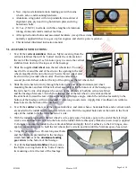
With the throttle servo in position, attach the th
rottle servo’s mount
to the inside of the fuselage with
5-minute epoxy.
33.
Cut away the Mylar covering material
from the wing’s hold-down bolt holes and from the correspond-
ing holes in the plywood wing hold-down plate.
34.
Connect
the rudder and elevator extensions, the throttle servo, and the receiver’s battery switch to
your
receiver
. If you are not setting up your radio for electronically-managed differential aileron response,
connect a Y-cable to your receiver’s aileron channel. If you have a computer-radio and will be setting up
aileron differential at your transmitter, connect two 6-inch servo extensions to the two channels you will
be using for aileron control. Wrap your receiver in cushioning foam rubber, position your radio receiver
on the radio tray and secure your radio receiver safely in position with criss-crossed rubber bands. (If you
are using a 72MHz. radio, route the antenna out of the fuselage and attach it to the top of the vertical stab.)
35.
Slide the two wing panels toward each other on their supplied
aluminum wing rod
. As these two panels
merge, allow them to self-align onto the factory-installed
wooden dowel-pins
.
36.
While holding the wing above the fuselage, connect the aileron’s extension wires to the corresponding
aileron wires attached to your receiver.
37.
Align and insert the plywood projections at the middle of the wing’s
leading edge with the opening behind the ‘windshield’ in the fuse-
lage, then gently lower the wing onto the fuselage’s wing saddle.
38.
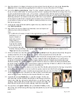
Place a flat washer onto each of the two (approx.
2 1/4-inch long)
wing hold down bolts
.
Guide the bolts (with their flat washers) through the
holes in the plywood wing hold-down plate, then into
and through the hold-down holes in the wing.
39.
With the wing squarely aligned in the wing saddle, drive
these bolts firmly (but not so tight that wood becomes
crushed) into the fuselage-mounted blind nuts at the rear
of the wing-saddle. Then, carefully lift the airplane and
lay it on its back on a soft surface.
40.
If you sometimes fly from asphalt or concrete, we
recommend you add a short length of
rubber tubing
(not included) at the outside-end of each axle to rub
against the wheel and cause friction – which acts as a
gentle ‘brake’ and helps reduce unwanted airplane
movement when you are landing and/or taxiing. This
friction is easily overcome during take-off by the
application of throttle.
41.
Slide a provided
mains-wheel
onto each of two
(approx. 1 1/2- inch long)
axle bolts
.
Twist a supplied hex-nut onto each axle bolt against
the hub of each wheel (and adjust it to compress the
rubber tubing, if used).
42.
Insert the remaining threaded end of each axle bolt
into the holes in the main landing gear struts.
Page 8 of 10


