


81
Reinstallation
3) Reconnect the fan power connector.
Push the fan casing up until it locks into place.
6-1B SMOOTHING CAPACITORS
A large-capacity aluminum electrolytic capacitor is used for smoothing the DC in the
main circuit, and an aluminum electrolytic capacitor is also used for stabilizing the
control power in the control circuit. Their characteristics are adversely affected by
ripple current, etc. When the inverter is operated in an ordinary, air-conditioned
environment, change the capacitors about every 5 years. When 5 years have elapsed,
the capacitors will deteriorate more rapidly.
Check the capacitors at least every year (less than six months if their life will be
expired soon).
Check the following:
1.) Case (side faces and bottom face for expansion)
2.) Sealing plate (for remarkable warping and extreme cracks)
3.) Explosion-proof valve (for excessive valve expansion and operation)
4.) Appearance, external cracks, discoloration, leakage. When measured
capacitance of he capacitor has reduced below 85% of the rating, change the
capacitor.
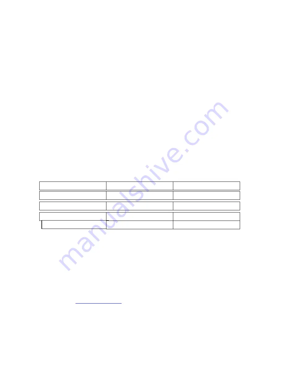
Figure 2
Time Replacement Chart
6-2
Relays
To prevent a contact fault, etc., relays must be changed according to the number of accumulative switching
times (switching life is approximately 30,000 rides).
6-3 Projector Bulb
To prevent an excessive down time, due to the projector bulb burning out, obtain a spare bulb whenever the
INFOCUS run time states over 750 hours. We do not know at this time how long this bulb lasts. This is
only a suggestion for having on hand this spare part, not a requirement.
Note: Projector bulbs can be obtained from Infocus direct by ordering from a local distributor or going on
the internet to (
WWW.INFOCUS.COM
). Also the projector is warranted by Infocus direct by a pass
through warranty. Any maintenance done to the projector will void the warranty. Should you require a
loaner, Infocus will overnight delivery you a loaner for a fee if given a major credit card.
Part Name
Cooling Fan
Smoothing Capacitor Main Ckt.
Smoothing Capacitor Control Brd.
Standard Replacement Interval
2 to 3 Years
5 Years
5 Years
Description
Change as Required
Change as Required
Change the board as requd.
Change as Required
Relays
-------------------
Summary of Contents for MT3000 ELECTRIC
Page 1: ...1 MaxFlight MT3000 ELECTRIC Monster Truck Manual ...
Page 8: ...8 MaxFlight MT3000 ELECTRIC Operators Manual ...
Page 25: ...25 MaxFlight MT3000 ELECTRIC Technical Manual ...
Page 57: ...57 USER JOYSTICK 0 AXES USER JOYSTICK 0 SLIDERS Calibration Buttons Calibration B tt ...
Page 58: ...58 Address EDS ...
Page 59: ...59 Path IO Drivers Game log and alert log routing information ithi th CPU ...
Page 60: ...60 Video Sound This is the page that the Occupant Safety Stop can be tested ...
Page 64: ...64 Regedit 32 Window Hkey Local Machine Window Start Run select Regedit32 enter ...
Page 65: ...65 Lift Motion Editor Settings Counterweight Motion Editor ...
Page 66: ...66 Counterweight Motion Cont Pitch Motion Editor ...
Page 67: ...67 Pitch Motion Filter 1 Editor Pitch Motion Filter 2 Editor ...
Page 68: ...68 Pitch Motion Filter 3 Editor Roll Axes Motion Editor Roll Motion Filter 1 Editor ...
Page 83: ...83 ...
Page 92: ...92 MaxFlight MT3000 Installation Manual ...
Page 98: ...98 ...
Page 99: ...99 ...
Page 100: ...100 ...
Page 101: ...101 ...
Page 102: ...102 ...
Page 103: ...103 ...
Page 104: ...104 ...
Page 105: ...105 ...
Page 106: ...106 ...
Page 107: ...107 ...
Page 108: ...108 ...
Page 109: ...109 ...
Page 110: ...110 ...
Page 111: ...111 ...
Page 112: ...112 ...
Page 113: ...113 ...
Page 114: ...114 ...
Page 119: ...Section IV Drawings A Electrical ...
Page 120: ......
Page 121: ......
Page 122: ......
Page 123: ......
Page 124: ......
Page 125: ......
Page 126: ......
Page 127: ......
Page 128: ......
Page 129: ......
Page 130: ......
Page 131: ......
Page 132: ......
Page 133: ......
Page 134: ......
Page 135: ......
Page 136: ......
Page 137: ......
Page 138: ......
Page 139: ......
Page 140: ......
Page 141: ......
Page 142: ......
Page 143: ......
Page 144: ......
Page 145: ......
Page 146: ......
Page 147: ......
Page 148: ......
Page 149: ......
Page 150: ......
Page 151: ......
Page 152: ......
Page 153: ......
Page 154: ......
Page 155: ......
Page 156: ......
Page 157: ......
Page 158: ......
Page 159: ......
Page 160: ......
Page 161: ......
Page 162: ......
Page 163: ......
Page 164: ......
Page 165: ......
Page 166: ......
Page 167: ......
Page 168: ......
Page 169: ......
Page 170: ......
Page 171: ......
Page 172: ......
Page 173: ......
Page 174: ......
Page 175: ......
Page 176: ......
Page 177: ......
Page 178: ......
Page 179: ......
Page 180: ......
Page 181: ......
Page 182: ......
Page 183: ......
Page 184: ......
Page 185: ......
Page 186: ......
Page 187: ...B Mechanical ...
Page 188: ......
Page 189: ......
Page 190: ......
Page 191: ......
Page 192: ......
Page 193: ......
Page 194: ......
Page 195: ......
Page 196: ......
Page 197: ......
Page 198: ......
Page 199: ......
Page 200: ......
Page 201: ......
Page 202: ......
Page 203: ......
Page 204: ......
Page 205: ......
Page 206: ......
Page 207: ......
Page 208: ......
Page 209: ......
Page 210: ......
Page 211: ......
Page 212: ......
Page 213: ......


