MAXDATA PLATINUM 2200 IR User Manual Download Page 15

15

MAXDATA Server PLATINUM 2200 IR M8

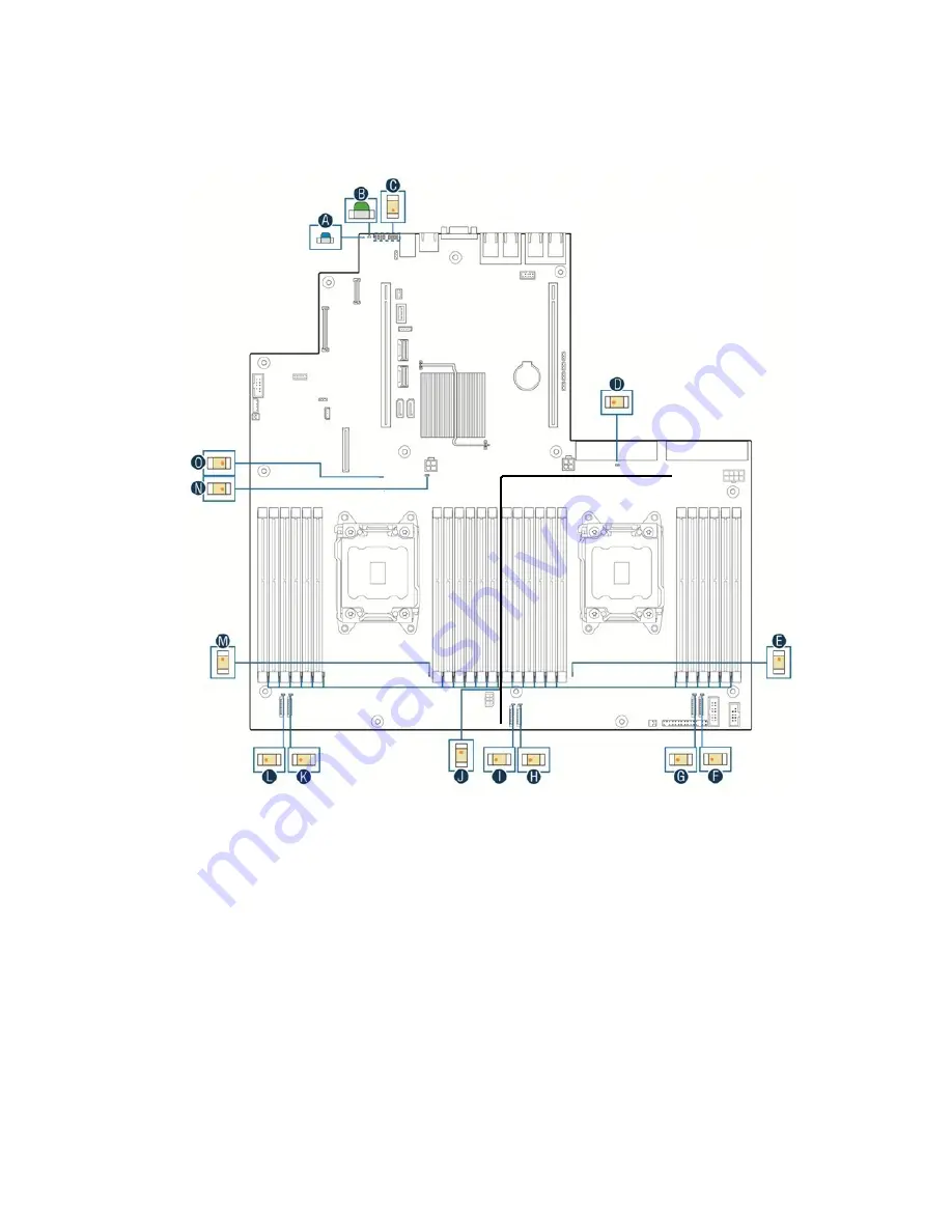
Light-Guided Diagnostics

The server board contains diagnostic LEDs to help you identify failed and failing components, and to 
help you identify the server from among several servers. Except for the ID LED, the status LED, and 
the 5V standby LED, the LEDs turn on (amber) only if a failure occurs.

Figure 5. Light-guided diagnostic LEDs

A.

System ID

I.

System fan 3 fault

B.

System status

J.

Memory fault

C.

POST code diagnostics

K.

System fan 2 fault

D.

12 V standby power present

L.

System fan 1 fault

E.

CPU 2 fault

M. CPU 1 fault

F.

System fan 6 fault

N. CATERR

G.

System fan 5 fault

O. System power good

H.

System fan 4 fault

Summary of Contents for PLATINUM 2200 IR

Page 1: ...User s Manual MAXDATA Server PLATINUM 2200 IR...

Page 2: ...2...

Page 3: ...d Upgrades 25 Before You Begin 25 Tools and Supplies Needed 25 System References 25 Removing and Installing the Chassis Cover 25 Removing and Installing the Front Bezel 26 Removing the Front Bezel 26...

Page 4: ...covering BIOS Defaults 43 6 Technical Reference 45 Power Supply Specifications 45 750 W Power Supply Input Voltages 45 Efficiency 45 750 W Single Power Supply Output Voltages 45 System Environmental S...

Page 5: ...ention device from a hot swap drive carrier 27 23 Attaching a hot swap hard disk drive to a drive carrier 28 24 Removing the air duct 29 25 Removing the PCI riser assembly 30 26 Installing the PCI ris...

Page 6: ...6...

Page 7: ...e not trip hazards When you save data to your server s hard disks or to a floppy disk they are stored as magnetic information on the media Make sure that they are not damaged by magnetic or electromag...

Page 8: ...2 K I O module optional E NIC 3 L Add in adapter slots via riser cards 1 and 2 F NIC 4 M Serial port B DB 9 optional G Video port Table 1 NIC LEDs LED LED state Description Left LED Off No network co...

Page 9: ...vailable on the control panel Figure 2 Control panel A ID button with ID LED B NMI button recessed tool required for use C NIC 1 activity LED D NIC 3 activity LED E Reset button F Status LED G Power b...

Page 10: ...PU 1 missing or failure voltage fault no memory present BMC video memory failure OFF AC power off powered down DC off state or S5 and no degraded non critical critical conditions exist HDD activity Gr...

Page 11: ...ntegrated storage controller unit SCU RAID upgrade keys supported for the SCU ports Peripheral interfaces External connections One DB 15 video connector 1 on back panel 1 on front panel with configura...

Page 12: ...th 750 W each Fans Five hot swap fans 60 mm 38 mm with n 1 redundancy One 40 mm fan for each power supply Server management Integrated IPMI 2 0 compatible baseboard management controller Support for R...

Page 13: ...wer connector AR BMC firmware force update jumper block P Main power slot 2 AS 2 pin hard drive activity LED header Q CPU 2 fan connector AT 4 pin IPMB connector R CPU power in and out connectors fact...

Page 14: ...s Figure 4 Configuration jumpers J6C4 J3A2 DCD DSR default J6C5 J6C6 J6D1 J2D1 BIOS Recovery Default Default Default Default Default Recover Clear Enabled Enabled ME force update BMC force update Pass...

Page 15: ...ept for the ID LED the status LED and the 5V standby LED the LEDs turn on amber only if a failure occurs Figure 5 Light guided diagnostic LEDs A System ID I System fan 3 fault B System status J Memory...

Page 16: ...Controller Configuration The AHCI Capable SATA Controller allows the following settings Enhanced supports up to two SATA devices in native IDE mode Compatibility supports up to two SATA ports in legac...

Page 17: ...ovides eight memory channels each with two S2600GL or three S2600GZ slots CPU socket 1 CPU socket 2 Channel A Channel B Channel C Channel D Channel E Channel F Channel G Channel H A1 A2 B1 B2 C1 C2 D1...

Page 18: ...ut S2600GZ The channels E to H which are asigned to CPU 2 can only be used when processor 2 has been configured If two processors are configured both processors can access the entire memory via Intel...

Page 19: ...CC UDIMM support Ranks and data width Capacity per DIMM Speed at 1 or 2 DIMMs per channel SR x8 or DR x8 1 2 4 8 GB 1066 1333 MT s Supported maximum memory configuration 128 GB 16 8 GB Table 5 RDIMM s...

Page 20: ...and 3 is mirrored The usable amount of memory is half of the installed memory Channels 0 and 2 as well as 1 and 3 must be populated with DIMMs of identical size and organization In Lockstep Channel mo...

Page 21: ...nt components and connections on the server chassis Component Identification Internal Components Figure 11 Internal component locations A Hot swap hard drive bays B Optical drive bay C Front control p...

Page 22: ...ive bay and front panel options Figure 12 3 5 hard drives 8 drive bays Figure 13 3 5 hard drives 12 drive bays Figure 14 2 5 hard drives 8 drive bays Figure 15 2 5 hard drives 16 drive bays Figure 16...

Page 23: ...us LED amber Off Drive bay not in use or no error On Hard drive fault Blinking 1 Hz RAID rebuild in progress Blinking 2 Hz Drive identification on B Activity LED green On SAS HDD powered on no activit...

Page 24: ...24...

Page 25: ...00 IR server chassis must be operated with the top cover in place to ensure proper cooling You will need to remove the top cover to add or replace components inside the chassis Before removing the top...

Page 26: ...Bezel 1 Unlock the bezel if it is locked 2 Remove the left end of front bezel from the rack handle A 3 Rotate the front bezel anticlockwise to release the latches on the right end from the rack handle...

Page 27: ...rrier Two screws are at each side of the retention device or the hard drive Store the plastic retention device for future use Figure 22 Removing the retention device from a hot swap drive carrier 5 Re...

Page 28: ...e the carrier from the chassis 4 Remove the four screws that attach the hard drive to the drive carrier Lift the drive from the carrier Store the drive in an anti static bag 5 If you are not installin...

Page 29: ...Carefully push in the two latches on the air duct A 2 Rotate the back edge of the air duct up to disengage the two tabs from the fan bulkhead B 3 Pull the air duct to the back and upwards away from th...

Page 30: ...nd unplug all peripheral devices and the AC power cable 3 Remove the chassis cover 4 Install any necessary add in cards into the PCI riser assembly 5 Install any cables onto add in cards that require...

Page 31: ...Remove the filler panel from the add in card slot and remove the screw A 6 Insert the add in card until it seats in the riser connector B 7 Secure the add in card with the screw you removed in step 5...

Page 32: ...or C 4 Secure the module with three screws D Figure 28 Installing an I O expansion module Installing a Solid State Drive Two SSDs or one SSD and one ODD can be installed in the server system 1 Remove...

Page 33: ...t have a redundant power supply installed you must power down your server system before replacing the power supply Removing a Hot swap Power Supply To replace the power supply use the following instru...

Page 34: ...with S2600GZ 24 DIMM mainboard Memory slot 3 needs to be populated on all memory channels 24 2 5 or 12 3 5 hard drive bay configuration Memory slot 2 and slot 3 on S2600GZ need to be populated on all...

Page 35: ...n off the server 3 Disconnect the AC power cord s from the server 4 Remove the chassis cover 5 Remove the memory and processor air duct 6 Locate the processor sockets see Figure 3 on page 12 7 Disconn...

Page 36: ...ter use Figure 35 Removing the protective cover from the load plate 12 Carefully lower the load plate over the processor to close it Figure 36 Closing the load plate 13 Latch the locking levers in rev...

Page 37: ...r 8 Lift the heat sink from the processor If it does not pull up easily twist the heat sink again Do not force the heat sink from the processor Doing so could damage the processor 9 Open the load plat...

Page 38: ...EMENT Danger d explosion en cas de remplacement incorrect de la pile Remplacez la uniquement par une pile du m me type ou d un type quivalent recommand par le fabricant Mettez au rebut les piles usag...

Page 39: ...cover and locate the battery 5 Gently push the metal tab to unlock the battery 6 Remove the battery from its socket Figure 38 Replacing the backup battery 7 Dispose of the battery according to local...

Page 40: ...40...

Page 41: ...een corrupted you will see other prompts but not the F2 prompt Warning CMOS checksum invalid Warning CMOS time and date not set In this condition the BIOS will load default values for CMOS and attempt...

Page 42: ...n the selected feature is a submenu or to display a pick list if a selected feature has a value field or to select a sub field for multi valued features like time and date If a pick list is displayed...

Page 43: ...he server and wait 10 seconds 6 Power down the server 7 Open the server chassis and move the jumper back to the default position covering pins 1 and 2 8 Close the server chassis 9 Power up the server...

Page 44: ...44...

Page 45: ...e DC converters on the mainboard Table 9 750 W power supply system output capability Voltage Maximum Current 12 V 62 A 12 V standby 2 1 A CAUTION The expansion slots on the server board are rated for...

Page 46: ...46...

Page 47: ...Directive 89 336 EEC European Union Product Regulatory Compliance Markings This product is marked with the following Product Certification Markings Table 11 Product certification markings CE Mark Pro...

Page 48: ...ms attached to the server before opening it The power supply cord s is are the main disconnect device to AC power The socket outlet s must be near the equipment and readily accessible for disconnectio...

Reviews: