background image

3257 HD

Series User’s Manual No:  UM

-3257-D2

   Page 11

+ I + I

G

G

1

2

+ I + I

G

G

3

4

+ I + I

G

G

5

6

+ I + I

G

G

7

8

Audio

Video

3.7

Unbalanced Audio (Single Ended)

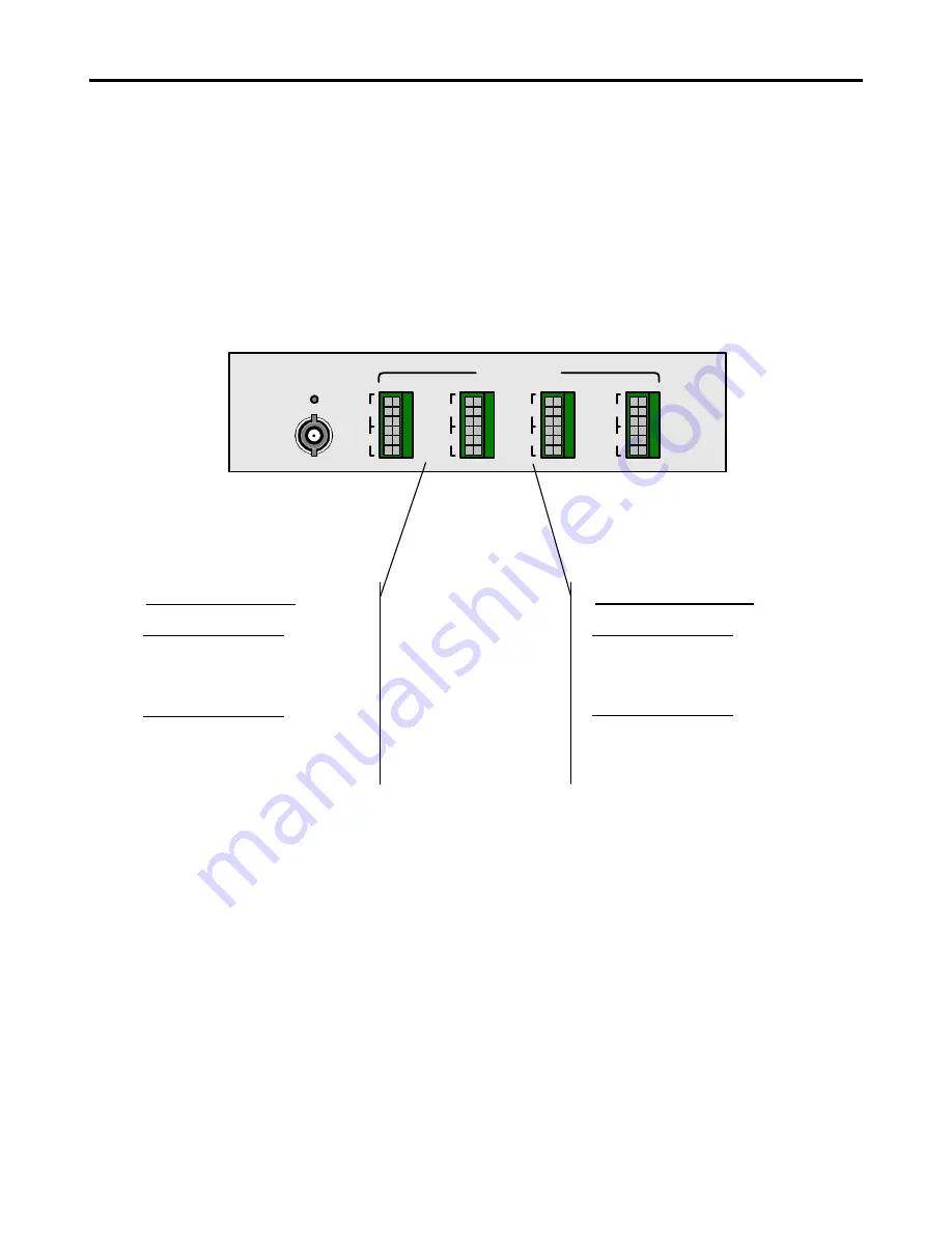
For  Unbalanced  audio  connections,  connect  the  audio  I/O  to  the  respective  “+”  and
“GND“leads on the output audio connector, as shown below.

Note:  Unbalanced Audio output will be 3dB less than input

Note:  DO NOT connect the (-) lead to ground on the audio OUTPUT as this may

create noise on the ground, which may distort the video signals.

Unbalanced Audio Input

Audio Channel  1, 3, 5, 7
Connect Ground to TB Pin 1
Connect Input + to TB Pin 2

Audio Channel  2, 4, 6, 8
Connect Input + to TB Pin 4
Connect Ground to TB Pin 6

Unbalanced Audio Output

Audio Channel  1, 3, 5, 7
Connect Ground to TB Pin 1
Connect Input + to TB Pin 2

Audio Channel  2, 4, 6, 8
Connect Input + to TB Pin 4
Connect Ground to TB Pin 6

Summary of Contents for MAX3257HD

Page 1: ...n MX3257HDT 1S 1V 2A ASI SCA 40 Fiber Optic Mux TX 1 Video 2 Audio 1 DVB ASI Singlemode SC APC Connector 40 Km MX3257HDR 1S 1V 2A ASI SCA 40 Fiber Optic Mux RX 1 Video 2 Audio 1 DVB ASI Singlemode SC...

Page 2: ...perature Operating 0C to 50C Storage 20C to 70C Humidity Operating 10 to 90 RH Storage 5 to 90 RH Input Power Requirements Voltage 90 240 VAC 47 63 Hz 2248 Meridian Ste H Minden Nv 89423 1 877 330 533...

Page 3: ...User s Manual MAX3257HD Series Video Audio Fiber Optic Multiplexing System Installation and User Guide...

Page 4: ...l Indicator Description 2 3 Rear Panel Indicator Description 3 INSTALLATION 3 1 General Installation 3 2 Power Connection 3 3 Fiber Optic Cables Connection 3 4 Video Connections 3 5 Audio Connections...

Page 5: ...r with the power turned on Exposure to Class IIIb Laser radiation is possible when the external fiber connector is disconnected while the unit is still powered up Ensure the rubber boot is in place wh...

Page 6: ...o 2 Channels Simplex Video and Simplex Audio 4 Channels Simplex Video and Simplex Audio 6 Channels Simplex Video and Simplex Audio 8 Channels DVB ASI 1 to 4 channels VIDEO AUDIO TECHNOLOGY The 3257 sy...

Page 7: ...itter 3257R 1 Channel Video Receiver 3257RSC 1 Channel Video 1 Channel Audio Sub Carrier Receiver 3257D 1 Channel Duplex Video 2 Channel Audio A Fiber Count 1 single fiber 2 two fiber B Fiber Type M M...

Page 8: ...s MAXCOM 2 2 Front Panel Indicators The following diagram depicts the front panel indicators Link Indicator Lights OFF TX Problem with Transmitter RX Problem with Optical Link Power Indicator Link Ind...

Page 9: ...UM 3257 D2 Page 7 2 3 Rear Panel Indicators The following diagram depicts the 3257T and 3257R rear panel configuration with optional audio channels installed NOTE Model Depicted is configured with 1 V...

Page 10: ...les in the sides of the 3257 Make sure that there is enough space to pull and connect both the electrical data and optical cables without stressing them beyond the manufacturer s limitation strain spe...

Page 11: ...nd return loss 3 4 Video Connections Video signals are sent over a 75 ohm coax cable terminated in a BNC connector e g RG 59U with a BNC connector a At the TX end 3257T connect the video source to the...

Page 12: ...strations below show how to connect balanced and unbalanced audio 3 6 Balanced Audio Differential For Balanced audio connections connect the audio lead to the respective audio channel input and the le...

Page 13: ...ill be 3dB less than input Note DO NOT connect the lead to ground on the audio OUTPUT as this may create noise on the ground which may distort the video signals Unbalanced Audio Input Audio Channel 1...

Page 14: ...audio sub carrier as an external signal The figure below depicts the 3257 set up with video 4 channels of Baseband audio and an external audio sub carrier channel The audio sub carrier channel uses a...

Page 15: ...ver a 75 ohm coax cable terminated in a BNC connector e g RG 59U with a BNC connector The DVB ASI I O will accept ANY PCM signal from 1Mbps to 600Mbps that is less than 1Vp p and is compatible with 75...

Page 16: ...er entry module to provide power via an IEC 3 prong cable 2 The indicator POWER on the front panel shows that the unit is properly powered 3 Install the fiber optic cables to the 3257 4 Verify that th...

Reviews: