background image

5.0   

SYSTEM SETUP 


www.maxcessintl.com 

MAGPOWR Spyder-Plus-S1 Tension Control 

MI 850A351 1 C  

Page 13 of 68 


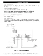
Connect Term.12 to Term.11 to switch to Manual mode. During Manual mode, the main output is directly controlled 
by the Manual setpoint analog input (Term.20).  
 

5.2.4 

TENSION ON/OFF 

Connect Term.13 to Term.11 to set the main output to 0 volts (4mA). Tension Off is always allowed for Load Cell 
and Open Loop Tension systems. For Dancer systems, Tension Off is only allowed when in Hold mode (Run/Stop 
Input = Stop). Tension Off overrides Manual mode. 


5.3 ANALOG OUTPUTS


5.3.1 

MAIN OUTPUT  

J6 configures the main output range for 0-10 VDC, -10 to +10 VDC, or 4-20 mADC. See Figure 4 for jumper 
settings. When using the -10 V to +10 V range be sure to configure the software for -10 V to +10 V output, use 
Normal for the other two ranges. See Section 6.2.2.3 or 7.2.2.5 or 8.2.2.5. The Spyder is configured from the 
factory for 0-10 VDC.


5.3.2 

METER OUTPUT (Load cell systems and Dancers with Load Cells Enabled and Open Loop Tension) 

A zero to 1 mADC signal proportional to Tension (Scaled to Max Tension) is available between Term.33 and 
Term.34 with Load Cell Systems and Dancers with Load Cells Enabled. For Open Loop Tension systems this 
signal is a 0 to 1 mADC signal proportional to the Diameter at Core divided by the Present Diameter to provide a 
relative speed signal to a motor on a rewind to keep the clutch power dissipation small. This output is driven by a 
0 to 10 VDC source in series with a 10K ohm resistor and can be used as a 0 to 10 VDC output when connected to 
a high impedance input.  


5.4 ANALOG INPUTS


5.4.1 

SETPOINT TENSION OR POSITION 

By default the Setpoint Tension or Position is input as a voltage between Term.16 and Term.17. Use the 
Configuration menu to change the setpoint to remote from the Ethernet port. As shipped from the factory, the input 
is calibrated for a pot between Term.15 and Term.17 with the wiper connected to Term.16. 

 
5.4.2 

MANUAL SETPOINT (Load cell systems and Open Loop Tension systems) 

The Manual Setpoint is input as a voltage between Term.20 and Term.21. As shipped from the factory, the input is 
calibrated for a pot between Term.19 and Term.21 with the wiper connected to Term.20. 


5.4.3 

DANCER POSITION (Dancer systems only) 

The actual Dancer Position is input as a voltage between Term.38 and Term.39. As shipped from the factory, the 
input is calibrated for a pot between Term.26 and Term.39 with the wiper connected to Term.38. See Section 7.3 
and Figure 12 for proper dancer potentiometer voltage with dancer movement. 

 
5.4.4     DIAMETER INPUT (All system types) 

The actual Diameter is input as a voltage between Term.38 and Term.39 for Open Loop Tension systems and 
Term. 35 and Term. 36 for Load Cell and Dancer systems. The input can take a voltage proportional to diameter up 
to 10 VDC. An input voltage of 0 volts is equal to a diameter of 0. See Section 6.6 (Load Cell), 7.4.3 (Dancer) or 8.3 
(Open Loop Tension) for calibrating diameter. 


Summary of Contents for MAGPOWR Spyder-Plus-S1

Page 1: ...Spyder Plus S1 Tension Control Instruction Manual Figure 1 Spyder Plus S1 EN MI 850A351 1 C MAGPOWR TENSION CONTROL...

Page 2: ......

Page 3: ...running output or vary based on diameter and or tension The dancer control is capable of controlling a dancer in unwind or rewind applications in any dancer system The dancer control output can be co...

Page 4: ...plete Wiring 22 6 9 Load Cell Control Diagram 22 7 0 DANCER CONTROL 23 7 1 Electrical Connections 23 7 2 Software Configuration for Dancer System 24 7 3 Dancer Input Setup Required 26 7 4 Dancer Calib...

Page 5: ...T 48 12 0 COMMUNICATION OPTIONAL 58 12 1 Network Setup 58 12 2 Parameters Available Only from the Web Page or Modbus TCP 58 12 3 Spyder Web Page 58 12 4 Update Software via FTP SITE 60 12 5 Spyder Con...

Page 6: ...oad Cells 21 Figure 9 Complete Load Cell System Wiring 22 Figure 10 Load Cell Control Diagram 22 Figure 11 Basic Dancer Wiring 23 Figure 12 DFP Connections 24 Figure 13 Dancer Torque with No Diameter...

Page 7: ...ke user manuals for proper settings The following is also required Power amplifier input if used 115 VAC for PS 90 or 24 VAC or VDC for PS 24 Output from power amplifier to clutch or brake The Spyder...

Page 8: ...olled In the Configuration menu also select if integrator control will be used and select the appropriate system type For large roll builds to use the gain compensated dancer control select Diameter U...

Page 9: ...ing for the clutch or brake being used Refer to amplifier and clutch or brake user manuals for proper settings The following is also required Power amplifier input if used 115 VAC for PS 90 or 24 VAC...

Page 10: ...Spyder provides an IP20 environmental degree of protection Wiring to and from the enclosure must be done with double or reinforced insulation or protective screening which provides protective separat...

Page 11: ...nd right arrow keys are used to edit selection choices for example to select system type In the tuning screens for dancer modes the up and down arrow keys are used to adjust the position of the dancer...

Page 12: ...wires from being pinched 2 Replace the cover 5 2DIGITAL CONTROL INPUTS J9 configures the control inputs for either 5 V or 24 V operation J8 configures the control inputs for either logic High or logi...

Page 13: ...o keep the clutch power dissipation small This output is driven by a 0 to 10 VDC source in series with a 10K ohm resistor and can be used as a 0 to 10 VDC output when connected to a high impedance inp...

Page 14: ...egative lead of the 24 VDC power input is Earth ground referenced See Figure 9 for complete connections See Figure 8 for connecting two MAGPOWR load cells Other load cells may also be used contact Fif...

Page 15: ...al and machine type and is totally subjective Determination of the correct amount of taper for your application is a trial and error process 6 2 1 4 MANUAL LEVEL This screen shows the manual level bei...

Page 16: ...mpensation 6 2 2 5 HOLD LEVEL CHANGE WITH Hold Level Output during Hold mode can be a fixed value or can vary with last running output multiplied by the Hold Level Multiplier or can vary based on diam...

Page 17: ...High The software is factory configured for Active Low inputs See Section 5 2 and Figure 4 6 2 2 9 INITIAL SCREEN The first screen after power up is the Operator Loop screen This parameter allows the...

Page 18: ...Maximum Tension to approximately twice the value of the normal running tension When finished press Enter the Applied Tension you will use to calibrate the load cells Press Apply the tension to the sen...

Page 19: ...icular message needs some comment Retune P at the present diameter not at core if P was previously tuned at core and this message repeatedly comes up For large roll builds the system may need to be Qu...

Page 20: ...the load cell control system is now complete See Section 9 0 for optional settings There is a table in section 9 6 6 showing default values of proportional integrator derivative error limit and stop...

Page 21: ...stem and when the system is stable select Cal Inertia to be Yes and press key to calibrate output versus torque Any diameter roll of material may be used when calibrating the output versus torque Diam...

Page 22: ...axcessintl com MAGPOWR Spyder Plus S1 Tension Control MI 850A351 1 C Page 22 of 68 6 8LOAD CELL SYSTEM COMPLETE WIRING Figure 9 Complete Load Cell System Wiring 6 9LOAD CELL CONTROL DIAGRAM Figure 10...

Page 23: ...t using the Ethernet port or the Setpoint screen Choose the Setpoint Source from the Configure menu Output to clutch or brake amplifier current to pressure transducer motor controller etc Route power...

Page 24: ...igation aid 7 2 1 OPERATOR LOOP MENU This section describes all of the screens in the Operator Loop menu All screens are display only 7 2 1 1 POSITION This screen shows the actual measured position in...

Page 25: ...ch or brake or motor in torque mode and Dancer Speed is for dancers using a speed device motor If a motor is used for a dancer system speed mode is recommended If a motor is used on an unwind system f...

Page 26: ...e 4 7 2 2 11 INITIAL SCREEN The first screen after power up is the Operator Loop screen This parameter allows the initial power up screen to be changed to either the Position screen Section 7 2 1 1 or...

Page 27: ...Dancer Back Move the dancer arm back to the stop with the minimum voltage This step verifies that the dancer potentiometer does not move past the end of the resistance element When the software deter...

Page 28: ...he web is stopped the Spyder automatically returns to the Tuning Menu when the web is stopped Make sure to set the position setpoint potentiometer to the midpoint before restarting after tuning NOTE A...

Page 29: ...lly steps through several separate stages in an attempt to stabilize the process The Quick Stab screens are all similar to this one Besides P the parameter being tuned can also be I The number next to...

Page 30: ...ll roll only after it has been optimized at core On rewinds Quick Stab may be needed to keep the system stable while a roll is wound See 7 5 3 3 for a typical tuning screen 7 5 3 2 Dancer Speed with a...

Page 31: ...b is stopped the Spyder automatically returns to the Tuning Menu when the web is stopped Make sure to set the position setpoint potentiometer to the midpoint before restarting after tuning NOTE Applie...

Page 32: ...the position setpoint potentiometer to the midpoint before restarting after tuning NOTE Applies to Setpoint Source is Ethernet The position setpoint can always be changed during tuning either by Ether...

Page 33: ...r Plus S1 Tension Control MI 850A351 1 C Page 33 of 68 7 8CONTROL DIAGRAM DANCER TORQUE WITH DIAMETER Figure 14 Dancer Torque with Diameter Control Diagram 7 9CONTROL DIAGRAM DANCER SPEED Figure 15 Da...

Page 34: ...7 0 DANCER CONTROL www maxcessintl com MAGPOWR Spyder Plus S1 Tension Control MI 850A351 1 C Page 34 of 68 7 10 Dancer System Complete Wiring Figure 16 Complete Dancer System Wiring...

Page 35: ...r input circuit is not isolated since the negative lead of the 24 VDC power input is Earth ground referenced An inverse diameter output is available on the meter output to control the speed of rewinds...

Page 36: ...E The desired Taper is dependent on material and machine type and is totally subjective Determination of the correct amount of taper for your application is a trial and error process 8 2 1 5 MANUAL LE...

Page 37: ...rcent This value may be changed either at the keypad the web page or by Modbus TCP Use the Setpoint Tension screen in the Operator Loop to change the tension setpoint 8 2 2 7 DIGITAL INPUT ACTIVE LEVE...

Page 38: ...Taper percent is set in the Operator menu See Section 8 2 1 4 Basic setup of the open loop tension system is now complete See Section 9 0 for optional settings 8 5OPEN LOOP TENSION CONTROL DIAGRAM Fig...

Page 39: ...nd must be calibrated to use taper tension Taper Percent Section 6 2 1 3 must be set to 0 zero to calibrate taper Navigate to the Taper Setup menu and Press Select Yes to enable Taper Press Enter the...

Page 40: ...3 3 Apply Maximum Setpoint Tension or Manual Voltage Apply the maximum Setpoint Tension or Manual voltage Press 9 3 4 Calibration Done The selected input calibration is now complete Press This will re...

Page 41: ...ake the system unstable or cause the position to overshoot 9 6 4 STOP TORQUE RATIO Dancer Torque with Diameter only In Dancer Torque with Diameter mode this parameter provides a control gain offset ne...

Page 42: ...MPENSATION PERCENT Used on Dancer Torque The value in percent added or subtracted to the output during stopping This value is modified by tension and last running level when diameter is not used and i...

Page 43: ...therefore different than the other digital inputs E Stop can also be mistakenly activated by selecting Digital Input Mode Active High when it is wired active low and the other way around See Section...

Page 44: ...s while using quick stabilize To diagnose 1 Go to the Output Level screen to read the average output while running in AUTO mode 2 Set the Manual Level to the average value 3 Go to the Tension screen 4...

Page 45: ...the dancer position signal varies smoothly using the Position screen in the Operator Loop Diameter not correct Diameter is not calibrated Calibrate diameter per section 7 4 3 The messages Re Tune P at...

Page 46: ...te load cells above Message Out of range at Max Tension The Spyder has calculated that the load cell will be overloaded if the Maximum Tension specified is applied to the sensing roll The Spyder will...

Page 47: ...e Probable Fault A TERM 25 P open B TERM 26 P open C TERM 25 P to TERM 23 S leg open D TERM 25 P to TERM 24 S leg open E TERM 26 P to TERM 23 S leg open F TERM 26 P to TERM 24 S leg open G TERM 25 P a...

Page 48: ...nual voltage Or Apply Min Set Manual voltage From Recal Inputs menu Calibration of the Tension Setpoint and Manual Level analog inputs Either input must be between 0 VDC and 10 VDC Min must be less th...

Page 49: ...orque device must be used Core Diameter From the Taper Setup menu for load cell system and the Parameter menu for Dancer Torque and Open Loop Tension systems Enter the value for the diameter of the co...

Page 50: ...See tuning procedure in section 6 4 or 7 5 First P at Full Then Mc at core From the Tuning menu for Dancer Torque with Diameter systems Selects which parameter to optimize See tuning procedure in sec...

Page 51: ...only The screen appears if the integrator was originally on and is now off If the system is now stable the instability was caused by the integrator A following series of screens explains this before...

Page 52: ...u Used to calibrate the tension meter output Term 33 to Term 34 when the tension is at Maximum Tension Modbus Address From the Network menu Sets the Modbus address of this Spyder Modbus Byte Order Fro...

Page 53: ...ers menu but that is not recommended Program Number From the Network menu The number of the program that will be downloaded from the FTP site to update the Spyder software Proportional Gain From the P...

Page 54: ...at Proportional Gain has been increased to the maximum allowed during tuning 50 Proportional Gain can be set higher than this using the Parameters menu but that is not recommended Secondary tuning is...

Page 55: ...t will dictate the control output during STOP mode Spyder will use the last control output sent during RUN mode before the STOP signal is received and multiply it by the value set here for the duratio...

Page 56: ...1 8 of their Maximum Tension This may mean that a load cell with too large of a rating has been installed Try smaller Max From the Cal Sensors menu The Spyder will suggest a Max Tension that will kee...

Page 57: ...igure menu Select Yes to enable reading of load cells when the Spyder is configured for a Dancer system Use Taper From the Taper Setup menu for Load Cell control or the Configure menu for Open Loop Te...

Page 58: ...12 2 PARAMETERS AVAILABLE ONLY FROM THE WEB PAGE OR MODBUS TCP The following parameters are text strings which are only available from the web page Text strings are limited to 31 characters Parameter...

Page 59: ...Spyder Status web page Figure 20 Spyder Configuration web page To change the value of a parameter click on the link for the data value The Spyder will return a page with an input box to allow enterin...

Page 60: ...et the SpyderWare installation kit from the Maxcess website This kit will install an FTP server on a Windows PC which can be used to download software to the Spyder 1 Go to www maxcessintl com 2 Type...

Page 61: ...ent the data Spyder Data Number Modbus Registers Comments BYTE 8 bit Unsigned Byte 1 High byte forced to 0 UINT16 16 bit Unsigned Integer 1 UINT32 32 bit Unsigned Integer 2 FLOAT 4 byte Floating Point...

Page 62: ...d Write 920Axxx yyy xxx yyy 0 999 xxx High Word yyy Low Word 0x0C FTP Directory STRING Data LC DTND DTD DS OPT Read Write 31 Characters Maximum 0x1C FTP User Name STRING Data LC DTND DTD DS OPT Read W...

Page 63: ...Multiplier FLOAT Data LC DTND DTD OPT Read Write 0 0 99 0 0x62 Hold Level FLOAT Data LC DTND DTD Read Write 0 0 100 0 0x64 Torque Output 0 Calibration Point 0 10V 4 20mA FLOAT Cal LC DTND DTD DS OPT...

Page 64: ...0 P 1 PI 0x8C Proportional Gain Dancer FLOAT Data DTND DTD DS Read Write 0 0 999 0 0x8E Integrator Time Dancer FLOAT Data DTND DTD DS Read Write 0 0 60 0 seconds 0x90 Initial Screen Load Cell BYTE Da...

Page 65: ...T None OPT Read Only 0 0 100 0 0xC2 Actual Tension Percent FLOAT None OPT Read Only 0 0 100 0 0xC4 Initial Screen Open Loop Tension BYTE Data OPT Read Write 0 Operator Menu 1 Tension 2 Output Level 3...

Page 66: ...T Data LC DTND DTD Read Write 0 0 999999 0 12 8 MODBUS MASTER PROGRAM There is a Modbus master program available to test communications with the Spyder that runs on a PC with Windows This program was...

Page 67: ...will be reset to defaults by holding down the and keys while turning on the power Hold the keys until the screen shows Resetting Parameters 13 3 Reset All Parameters to Defaults Including Calibration...

Page 68: ...um E Stop switch closure or 5 VDC or 24 VDC active High Low logic 8 mADC maximum Run Stop switch closure or 5 VDC or 24 VDC active High Low logic 8 mADC maximum Tension Off switch closure or 5 VDC or...

Reviews: