Maxatec MT-41 User Manual Download Page 5

6

7

2-2-1. Interface Connector


Serial Interface

PIN

SIGNAL

I/O

DESCRIPTION

3

TXD

Output

Printer transmit data line RS-232C level

2

RXD

Input

Printer receive data line RS-232C level

4, 7

DTR

Output

Printer handshake to host line RS-232C level

6

DSR

Input

Data Send Ready

5

GND

-

System Ground

USB Interface

PIN

SIGNAL

I/O

DESCRIPTION

1

+5V

-

+5V

2

DATA-

-

Printer transmit data line

3

DATA+

-

Printer transmit data line

4

GND

-

System Ground


<

RS-232

>

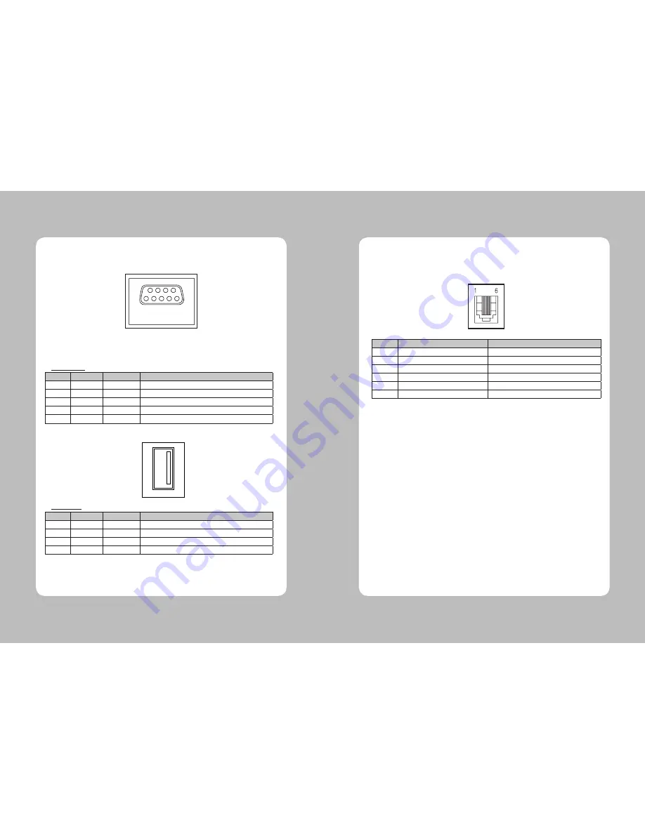
2-2-2. Cash Drawer Connector

The printer can operate two cash drawers with a 6 pin RJ-11 modular connector. 
The driver is capable of supplying a maximum current of 1.0A/24VDC for 510ms or less when not 
printing.

PIN

SIGNAL

DESCRIPTION

1

Signal GND

-

2

Drawer kick-out drive signal 1

Output

3

Drawer open/close signal

Input

4

+24V

-

5

Drawer kick-out drive signal 2

Output

6

Signal GND

-

Caution : To avoid an overcurrent, the resistance of the drawer kick-out solenoid must be 
               24

 Ω 

or more.

<USB>

Summary of Contents for MT-41

Page 1: ...All specifications are subject to change without notice Receipt Printer User s Manual MODEL MT 41...

Page 2: ......

Page 3: ...imal Dump 15 6 Speci cations 16 6 1 General Speci cations 16 6 2 Auto Cutter Speci cations 18 6 3 Interface 18 6 4 Electrical Characteristics 18 6 5 Environmental Requirements 19 6 6 Reliability 19 6...

Page 4: ...necting the Cables You can connect up the cables required for printing to the printer They all connect to the connector panel on the back of the printer which is shown below Before connecting any of t...

Page 5: ...nsmit data line 3 DATA Printer transmit data line 4 GND System Ground RS 232 2 2 2 Cash Drawer Connector The printer can operate two cash drawers with a 6 pin RJ 11 modular connector The driver is cap...

Page 6: ...ectly 2 3 1 Turn off power switch 1 Make sure that the printer is not receiving data Otherwise data may be lost 2 Open the paper roll cover by pushing down the cover open button 3 Remove the used pape...

Page 7: ...ng XON XOFF DTR DSR OFF DIP Switch Functions 2 Baudrate selection Transmission speed SW 7 SW 8 11520 bps ON ON 9600 bps OFF ON 19200 bps ON OFF 38400 bps OFF OFF DIP Switch Functions 3 Print Density P...

Page 8: ...ol panel The indicator lights help you to monitor the printer sstatus Control Panel Button The button can be disabled by the ESC c 5 command Press the FEED button once to advance paper one line You ca...

Page 9: ...to receive data as soon as it completes the self test This feature allows experienced users to see exactly what data is coming to the printer This can be useful in finding software problems When you...

Page 10: ...t against electrostatic AC line noise etc 6 1 General Specifications 1 Printing Method Direct line thermal printing 2 Print speed 140mm sec 3 Dot density 203 DPI Hor Ver 203 203 0 125mm 0 125mm dot 4...

Page 11: ...ly of DC 24V 10 and more than 2 5A 2 Be careful about installing the printer in an area where there is noise 3 Take the appropriate measure to protect against electrostatic AC line noise etc 6 5 Envir...

Page 12: ...sor s to output paper end signals 36 ESC c 4 Select paper sensor s to stop printing 37 ESC c 5 Enable disable panel buttons 38 ESC d Print and feed paper n lines 39 ESC p General pulse 7 Command List...

Page 13: ...22 23...

Page 14: ...Rev 1 0...

Reviews: