background image

9

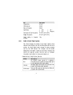
Item

Descriptions

Propeller Size

9.4”x4.3”

WiFi Frequency

2.4GHz

Receiver Frequency

5.8GHz

Flight Modes

z

GPS

z

IOC

z

ATTI

z

Waypoint

Operating Environment Temperature

0

q

C~50

q

C (32

q

F~122

q

F)

Storage Temperature

0

q

C~45

q

C (32

q

F~113

q

F)

Weight (Battery & Propellers 
included)

1.1kg

2.2.2

Built-in Smart Flight System

The X-Star features the Built-in Smart Flight System which 

enables autopilot flight control that provides great ease of use and 

stability. The Smart Flight System consists of various modules 

such as the GPS receiver, the Compass and the Inertial 

Measurement Unit (IMU). It works as the central computer of the 

aircraft and supports various functions such as Intelligent 

Orientation Control (IOC), Go Home, and Failsafe, etc.

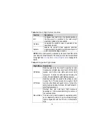
Table 2-3

Smart Flight System Modules

Module

Descriptions

IMU

An electronic device consists of a gyroscope, 
accelerometer and magnetometer that measures flight 
velocity, gravitational force and orientation.

Compass

Reads geomagnetic information and assists the GPS 
receiver for accurate position calculation.

GPS Receiver

Receives GPS signals and determines the latitude and 
longitude of the aircraft location.

Summary of Contents for X-Star ST1

Page 1: ...available at the time of printing Maxaero reserves the right to make changes at any time without notice While information of this manual has been carefully checked for accuracy no guarantee is given t...

Page 2: ...ecially when taking off and landing z Remove the batteries before assembly or when not in use z Keep away from the moving and powered parts especially rotating propellers z Remove all propellers durin...

Page 3: ...plosion or other hazards z Disconnect and remove the Li Po battery from the aircraft after use to prevent trickle discharge During storage make sure the battery charge does not fall below 3V z Stop us...

Page 4: ...keep the battery within normal temperatures z Completely discharge the battery prior to disposal z Dispose of the battery properly For Services and Support http www maxaero com 0086 755 86147779 Chin...

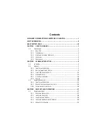
Page 5: ...1 FUNCTIONAL DESCRIPTION 7 2 2 2 BUILT IN SMART FLIGHT SYSTEM 9 2 2 3 FLIGHT LED INDICATOR LIGHT 11 2 2 4 AIRCRAFT BATTERY 12 2 2 5 3 AXIS CAMERA GIMBAL 16 2 2 6 CAMERA 18 2 3 REMOTE CONTROLLER 20 2...

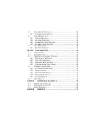
Page 6: ...NG COMPASS 41 4 3 REMOTE CONTROLLER AND FLIGHT OPERATIONS 43 4 3 1 MOTOR START UP AND TAKE OFF 43 4 3 2 FLIGHT ATTITUDE CONTROLS 44 4 3 3 LANDING AND MOTOR SHUT DOWN 47 4 3 4 OPERATIONS OF SMART FLIGH...

Page 7: ...ventions are used 1 1 1 Bold Text Bold emphasis is used to highlight selectable items such as buttons and menu options Example z Tap OK 1 1 2 Terminology The term select means highlighting a button or...

Page 8: ...cuments Blue colored text indicates a selectable hyperlink 1 1 5 Procedures An arrow icon indicates a procedure Example To use the camera 1 Tap the Camera button The camera screen opens 2 Focus the im...

Page 9: ...edibly versatile and powerful This manual describes the construction and operation of the product and how it works to deliver flight maneuvers for ideal aerial photographing solutions 2 1 In The Box T...

Page 10: ...es 25 minutes of flight time if fully charged X1 Aircraft Battery Charger Connects the Aircraft Battery to the external power port for AC DC power supply X1 Micro USB Cable z Connects the Remote Contr...

Page 11: ...Lock Pins Fix the Camera Gimbal to the mounting rack connected to the aircraft to avoid dropping 2 pins mounted on deliver 2 extra supplied for maintenance use X4 Vibration Absorber Fixed in between...

Page 12: ...tor X1 Camera Battery 940mAh Rechargeable Li Po Battery installed on delivery X1 Flat Mount X1 Curved Mount X2 Short Connectors X1 Long Connector X1 90qC Rotate Connector long X1 90qC Rotate Connector...

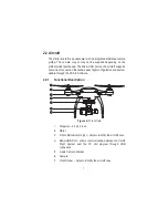
Page 13: ...n that allows easy flight configuration and system update through the PC Aid Software 2 2 1 Functional Description Figure 2 1 Front Side 1 Propeller 9 4 x 4 3 inch 2 Motor 3 Front LED Indicator Light...

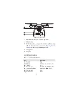
Page 14: ...iring Remote Controller on page 33 for detailed instructions 11 Landing Gear 12 Compass Aircraft Specifications Table 2 2 Aircraft Specifications Item Descriptions Max Payload 0 8kg Hover Precision Ho...

Page 15: ...stem consists of various modules such as the GPS receiver the Compass and the Inertial Measurement Unit IMU It works as the central computer of the aircraft and supports various functions such as Inte...

Page 16: ...2 5 Supported Flight Modes Flight Modes Descriptions GPS Mode Stabilizes and holds the aircraft in position on stick release when activated requires at least 6 GPS satellite signals which offers more...

Page 17: ...t Indicates flashing light R Indicates red colored light G Indicates green colored light Y Indicates yellow colored light Example R stands for RED SOLID light Table 2 6 Definitions of Flight LED Indic...

Page 18: ...y caused by z IMU deviation or abnormal z Compass error z Remote Controller recalibration required See 5 2 Troubleshooting Checklist on page 83 for detailed information 2 2 4 Aircraft Battery The Airc...

Page 19: ...ange Low Battery Protection Activates alarm when battery level is less than 20 LED Capacity Indicator Indicates current battery level Overcharging Over discharging Protection z Automatically stops cha...

Page 20: ...mAh Battery Voltage 11 1V Charging Environment Temperature 0qC 40qC 32qF 104qF Discharging Environment Temperature 20qC 60qC 4qF 140qF Storage Temperature Humidity Temp 10qC 45qC 14qF 113qF Humidity 5...

Page 21: ...or 3 seconds C To check the current battery level when the battery is powered off short press the Power Button once and the Capacity Indicator Lights will illuminate and indicate the current battery l...

Page 22: ...Aircraft Battery and therefore it is turned on at the same time with the aircraft A self test is performed each time the Gimbal starts up The X Star system is compatible with more than one gimbal mode...

Page 23: ...Do not disconnect the camera from the gimbal while transferring Camera Gimbal Specifications Table 2 10 Camera Gimbal Specifications Item Descriptions Operating Current 340mA 12V Camera Off 600mA 12V...

Page 24: ...era The Camera mounted to the Aircraft is stabilized by the 3 axis Camera Gimbal Depending on the gimbal s working mode applied it enables both real time FPV piloting control and smooth aerial photogr...

Page 25: ...n off the camera C When the camera is powered on pressing this button allows you to switch among the camera Modes the Playback and the Setting options in sequence 3 WiFi Status Light blue Indicates th...

Page 26: ...move the lens cap before use Camera Specifications Table 2 12 Camera Specifications Item Descriptions Operating Environment Temperature 10qC 50qC 14qF 122qF Effective Pixels 12MP HD Recording Resoluti...

Page 27: ...d when the aircraft the Remote Controller and the mobile device are properly connected through WiFi connection See 3 3 3 Establishing X Star WiFi Network on page 35 for detailed instructions 2 3 1 Fun...

Page 28: ...Mobile App 2 Mobile Holder Holds the mobile device with the X Star Mobile App installed with up to 90 q adjustable viewing angle for optimum visibility 3 Indicator Light Panel Indicates different sta...

Page 29: ...en the remote controller is turned on See 2 3 2 Remote Controller Indicator Lights on page 24 for detailed information 10 Take off Button When the motors start up pressing this button for 3 seconds co...

Page 30: ...the remote controller operations NOTE The Remote Controller makes an alert sound after 15 minutes of inactivity and turns off automatically after 30 minutes of inactivity 2 3 2 Remote Controller Indic...

Page 31: ...ircraft battery level is less than 20 2nd Level Low Battery Protection activated z Shows red light when the aircraft battery level is less than 10 1st Level Low Battery Protection activated RF Signal...

Page 32: ...iptions Operating Frequency RF Receiver 5 8GHz WiFi Repeater Frequency 2 4GHz Operating Temperature 0qC 50qC Storage Temperature 20qC 75qC Communication Distance open area CE 400m FCC 800m Transmissio...

Page 33: ...injuries IMPORTANT Do not use with incompatible components or alter this product in any way inconsistent with this manual failure to operate this product in a safe and responsible manner could result...

Page 34: ...he propellers Name Icon Description Lock Icon Fasten the propeller by rotating the propeller in the indicated direction Unlock Icon Unfasten the propeller by rotating the propeller in the indicated di...

Page 35: ...onnect the supplied Aircraft Battery Charger to the wall socket 2 Connect the battery to the charger The Capacity Indicator Lights will illuminate and indicate the battery level during charging See Ta...

Page 36: ...evel 95 80 50 25 25 3 1 4 Installing and Removing the Battery To install the battery 1 Make sure the battery is powered off before installation 2 Insert the battery into the aircraft battery compartme...

Page 37: ...ed manually by the user before flight To mount the camera 1 Align and connect the Mini USB Port on the camera to the Camera Connector on the gimbal 2 Align the upper and lower screw holes of the Camer...

Page 38: ...he USB Power Adapter using the Micro USB Cable supplied 2 Plug the USB Power Adapter to the wall socket 3 The Power Button on the remote controller will show flashing red light during charging When ch...

Page 39: ...t as CE compliant whereas 3 brief buzz sounds can be heard when set as FCC compliant 3 Turn on the WiFi switch at the rear side of the remote controller The remote controller retrieves flight data whi...

Page 40: ...for a few seconds the pairing indicator will change from slow flashing light to quick flashing light when pairing is successful 3 3 Preparing Mobile Device By connecting your mobile device to the X St...

Page 41: ...plication will be installed onto your mobile device NOTE The X Star application will be regularly updated Please check occasionally for latest updates 3 3 2 Registering User Account When the X Star Mo...

Page 42: ...the X Star WiFi Network connection fails or either the aircraft or the remote controller is replaced and re paired the X Star WiFi Network will need to be re established as well Re pair the X Star Wi...

Page 43: ...nter the Pairing page Figure 3 5 9 Tap MAC button to manually enter or scan the MAC code of the aircraft NOTE By scanning the QR code at the bottom of the aircraft the SSID and the MAC address will be...

Page 44: ...ill load momentarily 2 Click Next on the welcome page 3 Click the Change button and select a destination folder to install the program and click Next to continue Or directly click Next to continue wit...

Page 45: ...gin Prompt After successful registration enter your X Star username and password to sign in the PC Aid operation program See 4 5 PC Aid Operations on page 79 for detailed operation instructions of the...

Page 46: ...cklist Follow the steps below to carry out a full preflight check up to get ready for the first flight Check up before flight 9 The camera is stably mounted to the gimbal 9 The camera lens cap is remo...

Page 47: ...compass deviation indicating that compass calibration is required IMPORTANT The compass is very sensitive to electromagnetic interference which may cause compass error leading to poor performance or f...

Page 48: ...Hold the aircraft vertically with the nose down and rotate for 360q around The LEDs on the aircraft will display normally in correspondence to the current flight mode when calibration is completed suc...

Page 49: ...n different flight modes GPS or ATTI mode See Table 2 5 on page 10 for details NOTE Do not fly in GPS mode when less than 6 satellite signals are received In this case the aircraft will not be able to...

Page 50: ...s sent successfully Once the command is sent the aircraft ascends automatically and starts hovering when it reaches the height of 2 meters 4 3 2 Flight Attitude Controls The aircraft reacts to the con...

Page 51: ...o ascend by pushing the stick upward and descend by pushing it downward Figure 4 4 Throttle Control Aircraft Left Side View B Rudder commands the aircraft to yaw left or right by pushing the Rudder le...

Page 52: ...C Elevator commands the aircraft to pitch up and down to move forward or backward by pushing the Elevator upward or downward Figure 4 6 Elevator Control Aircraft Left Side View Rudder left Nose Yaws L...

Page 53: ...aft may be landed manually automatically or passively depending on different circumstances IMPORTANT The aircraft must be landed gently on a flat surface to avoid damage z Manual landing Pilots may ma...

Page 54: ...ttom corners simultaneously either toe in or toe out for a few seconds to stop the motors Figure 4 3 5 Release the stick s gently and simultaneously after the motors have stopped spinning z Automatic...

Page 55: ...level reaches 10 or lower to avoid accidents and damages z Passive landing when Failsafe is activated When the Failsafe function is activated the aircraft will perform Go Home if GPS is available or...

Page 56: ...t If the aircraft is getting closer within 10 meters boundary from home point Home Lock mode will be automatically switched to Course Lock mode NOTE The flying direction is relative to the starting po...

Page 57: ...ontrol B When Go Home is activated by Failsafe There are 2 ways to regain control 1 Press and hold the Take off button on the remote controller for 3 seconds A brief beep sound can be heard when the c...

Page 58: ...reen lights for 3 seconds indicating the reset is successful z Failsafe The Failsafe function will be activated after 5 seconds when communication between the aircraft and the remote controller is los...

Page 59: ...ess control B Flight Data Display displays parameters of z Flight z Gimbal z Remote Controller z IMU Modules z Aircraft Battery C Ground Station Navigation programs GPS waypoint navigation missions an...

Page 60: ...lows data synchronization for image display and camera pairing for FPV or non FPV navigation Ground Station Allows to locate the aircraft and perform waypoint navigation and flight settings Configurat...

Page 61: ...n screen Figure 4 10 tap the Camera button on the Main Menu Figure 4 10 Camera Operation Screen 1 Pitch Control Panel 2 Status Information Bar 3 Camera Operation Panel 4 Ground Station Split Screen z...

Page 62: ...s of 8 items The features of each item are described respectively from left to right as follows 1 Pitch Angle indicates the camera pitch angle 2 Flight Altitude indicates planned flight height 3 Fligh...

Page 63: ...ooting 3 Shooting Button displays the current camera mode tapping which allows to execute the selected camera mode action 4 Hide Display tap to hide the flight information bar and the pitch control pa...

Page 64: ...4 11 Camera Settings Panel The functions of each setting option are described in the table below Table 4 3 General Camera Settings Settings Button Options Resolution 1080P 16 9 default 960P 4 3 720P...

Page 65: ...ard 1 Tap the Camera Settings button on the right side of the screen to open the Settings Panel 2 Tap Format button and a prompt will appear to remind you that all data in the Micro SD card will be de...

Page 66: ...ate the recording is in progress and a time code will appear in the upper right corner of the preview screen 3 Press the Shooting button again to stop recording To view the saved photos or videos 1 Pr...

Page 67: ...rogram Figure 4 12 Ground Station Operation Screen NOTE Make sure your mobile device is connected to the internet when using this function for the first time to allow auto installing of the maps 1 Con...

Page 68: ...plays the following items from left to right 1 Flight Mode indicates the current flight mode 2 Flight Altitude indicates planned flight height 3 Current Aircraft Distance indicates the distance betwee...

Page 69: ...ration procedure Map View Allows choosing a desired map view Normal Hybrid or Satellite view Locator Locates the current home point retrieved from X Star system on the map When aircraft GPS data is no...

Page 70: ...during Ground Station operation Tapping the thumbnail allows users to quickly switch to the camera operation screen z Waypoint Operations Tapping the Waypoints button on the Control Panel opens launc...

Page 71: ...ints Removes the selected waypoint one by one Move Waypoints Moves the waypoint position one at a time Delete Waypoints Deletes all waypoints Safety Zone N A Refers to the area within the circle The a...

Page 72: ...rcraft by pushing the Flight Mode Switch on the remote controller to ATTI position The aircraft will abort the mission and respond to the navigation by the remote controller 2 Tap the Go Home button t...

Page 73: ...r Mobile App Figure 4 14 Configuration Operation Screen z Flight Limits All unmanned aerial vehicle UAV pilots should comply with all regulations from ICAO International Civil Aviation Organization an...

Page 74: ...tricted to the preset height limit For distance limit under non GPS mode it may be various depending on the regulations and laws in different areas and countries NOTE Under GPS mode the maximum flight...

Page 75: ...stabilized camera tilting control B FPV Mode synchronizes the camera gimbal movement with the aircraft z Flight Parameters The Flight Parameters option is used to tune the systemic parameters of the...

Page 76: ...Remote Controller The Remote Controller function enables the pilots to choose preferred transmitter modes calibrate command sticks and testify if the Smart Control Switch and the Flight Mode Switch wo...

Page 77: ...Transmitter Modes Section There are 3 transmitter modes Mode 1 Mode 2 and Mode 3 Each mode indicates how the movement of command sticks controls the actions of the aircraft correspondingly Below are t...

Page 78: ...eron Elevator Throttle and Rudder respectively Before calibration make sure your desired transmitter mode has been selected To calibrate the command sticks 1 Turn on the remote controller and then the...

Page 79: ...r switch group allows testing of the Smart Control Switch which includes Normal IOC and Go Home modes The lower switch group allows testing of the Flight Mode Switch which includes GPS ATTI and ATTI m...

Page 80: ...30 meters height to reduce risks of crashing or damages If the aircraft altitude is higher than 30 meters then the aircraft will remain at its height level and returns to the home point with the short...

Page 81: ...y screen as below Figure 4 21 Battery Screen The displayed battery information includes the following items 1 Current Status displays voltage and current values of the aircraft battery 2 General Infor...

Page 82: ...l Intelligent Orientation Control IOC is a smart feature that helps the pilot to navigate the aircraft without worrying about its nose direction This is very helpful for new pilots to regain control o...

Page 83: ...modes z View Status Tapping View Status from the main menu displays an information screen which presents an overview list of the configuration status of the X Star system 4 4 5 Settings Operations The...

Page 84: ...compass calibration 4 Low Battery Auto Return slide the button to enable or disable the auto return function for low battery protection 5 FPV Mode slide the button to activate or deactivate the FPV mo...

Page 85: ...rcraft gimbal and remote controller on the PC Launch the PC Aid program after installation is complete After logging in to your PC Aid account a prompt screen will appear to remind you to connect the...

Page 86: ...er flight The items may vary according to the specific tag selected on the Menu Bar z Main Screen This section which occupies a great part of the display area on the PC Aid operating screen shows vari...

Page 87: ...or easy aircraft navigation when its orientation is uncertain View Status N A Displays current configuration status of the X Star system Table 4 9 Functional Buttons under the Gimbal Tag Name Button D...

Page 88: ...work if it is moist or if you tap it with wet hands y Do not store the devices in humid dusty or dirty areas y Do not attempt to disassemble your devices y Use a soft cloth with alcohol or a mild wind...

Page 89: ...ated B When the aircraft motors fail to start up 9 Check if the remote controller and the aircraft are properly paired 9 Check if the remote controller parameters are properly calibrated C When take o...

Page 90: ...Check if both the aircraft and the remote controller are powered on 9 Make sure WiFi is enabled on both the mobile device and the Remote Controller I If the aircraft is out of sight and the Wi Fi con...

Page 91: ...e remote controller 5 3Service Procedures This section introduces information for technical support repair service and application for replacement or optional parts Technical Support If you have any q...

Page 92: ...the device to your local agent or to the following address 6th 10th Floor Building B1 Zhiyuan Xueyuan Road Xili Nanshan Shenzhen 518055 China Other Services You can purchase the optional accessories...

Page 93: ...to follow the safety instructions presented throughout the manual will void the warranty of the product Some states or countries do not allow limitations on how long an implied warranty lasts so the...

Page 94: ...to part 15 of the FCC Rules These limits are designed to provide reasonable protection against harmful interference in a residential installation This equipment generates uses and can radiate radio f...

Reviews: